Last week I did some repair work at WDDY in Albany NY. It seems the sample line on one of the towers was melted in half by a lightning strike. This station uses sample loops up on the tower for its directional antenna monitoring system.
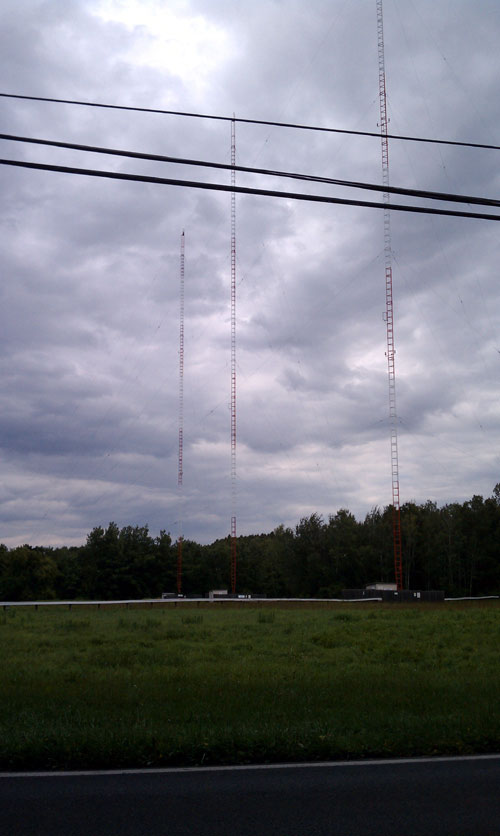
WDDY antena array, Albany, NY
As it happened, the sample line in question was on the reference tower, which makes everything else meaningless. Before the meltdown, there were several years’ worth of maintenance logs that showed the previous values for current ratio and phase relationship.
With the transmitter turned off and locked out, I removed the damaged section of the line from the base of the tower to the RF choke coil in the tuning house. Where the sample line came off of the base of the tower, there was a UHF-type connector that had been improperly applied. Using spare parts, I fixed that connector, then spliced the line into place. Upon power-up, the transmitter and antenna readings returned to their previous values, which were slightly out of tolerance.
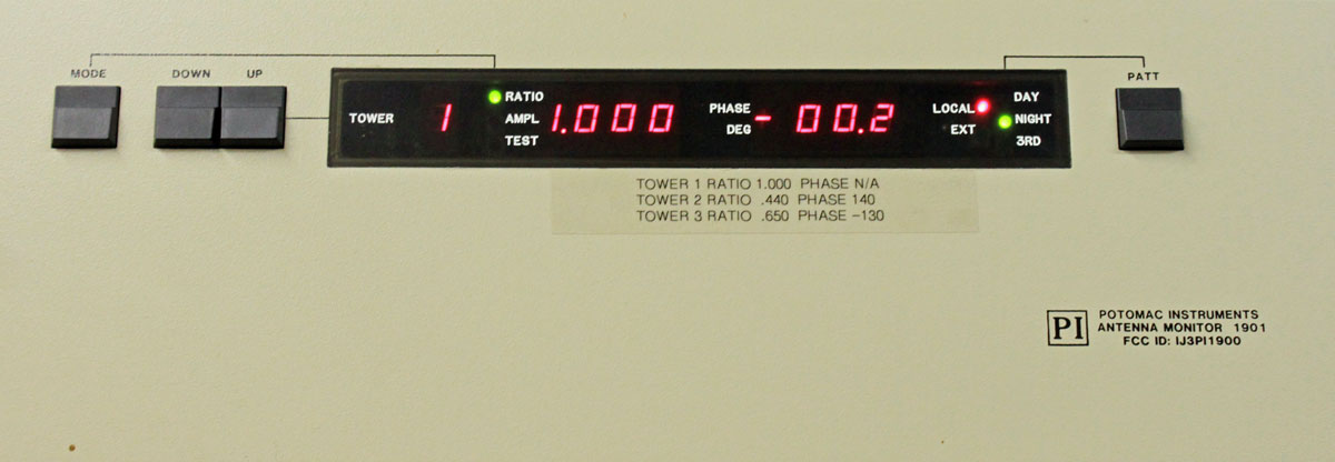
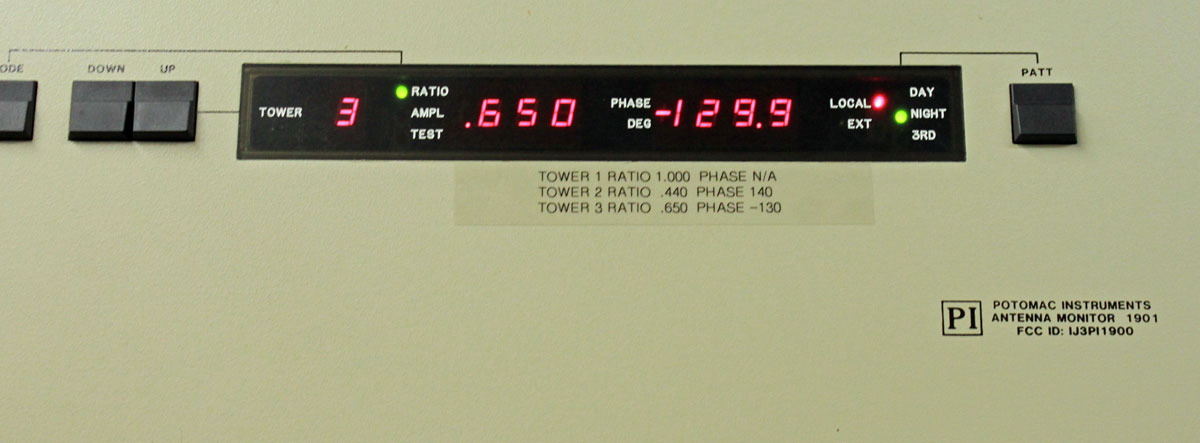
Thus, some phasor tuning was needed. There are not too many people left that can properly tune an AM phasor. All of the control interact with each other; moving the power or phase to one tower will likely affect all of the other towers and possibly the reflected power on the transmitter. This phasor was made in the 1970s by Multronics with what looks like all RCA parts. Multronics, I think, was John Mullaney who is more known for the folded unipole antenna. In any case, after a good few hours of careful hand cranking and a run out to the reference tower to move a coil tap, here are the results:
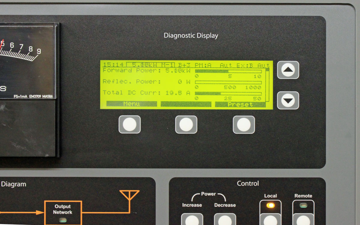
WDDY tower one, referenceWDDY tower twoWDDY tower threeWDDY forward/reflected power
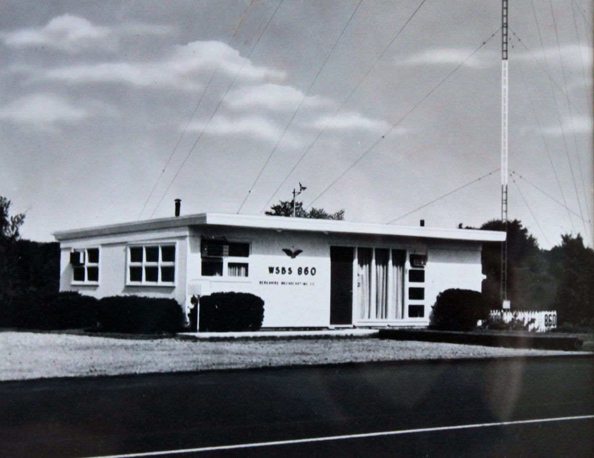
Alan asked if I should ever find a picture of the old WSBS studio building to publish it. Here it is:
WSBS old studio building
I found this above the coffee machine in the lobby, nicely matted and framed. I didn’t want to ruin the framing job, so I took a picture of the picture under glass and cropped it, so thus the quality could be better.
I believe this is the original tower from 1959. The current tower stands on a taller concrete pedestal and is further away from the road. I think the roadway was widened and raised at some point, thus the new building sits higher in relation to the tower base. In any case, it little bit of radio history.
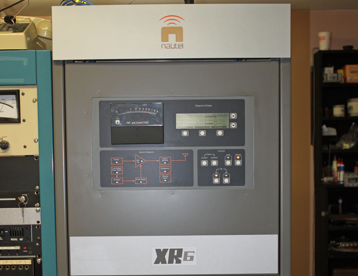
I’ve been away working in Burlington, VT (WVMT, 620 KHz, Burlington) for the last coupla, installing this nifty Nautel transmitter:
Nautel XR6 transmitter, WVMT Burlington, VT
I like the Nautel units, both AM and FM; they are well-designed, well-built, rugged transmitters. I have lost track of how many of these units we service in the field, partly because they are becoming pretty much standard equipment at all of our installations.
Continental 315R-1 AM transmitter, WVMT, Burlington, VT
The transmitter it is replacing is a Continental 315R-1, which is based on the Collins Power Rock design. It is a PWM transmitter with a 15,000 volt power supply. In their day, these were not terrible transmitters, however, like their Harris MW-5/10/50 PDM brethren, frequent thorough cleaning is required to keep the dirt/dust from arcing over. Unfortunately, it is becoming more and more difficult to obtain parts for these units. This transmitter was installed in October of 1983, thus, almost thirty years of service is quite enough. This unit we did not cut up and scrap, rather, it is sitting by the back door, waiting for any takers.
Continental 315R-1 modulator/RF sections
The interior of the Continental 315-R1 transmitter. Modulator section is on the left, RF section is on the right.
The good news is, WVMT is another one of those “successful AM station” stories. You know, the kind of station that has local programming, local sports, news, community presence and most importantly, makes money. For all those diligently studying the “AM Problem” for the up and coming NAB conference this April, here is a clue: It’s the programming…
Nautel XR6 transmitter, WVMT Burlington, VT
This is the Nautel XR-6 on the air. Positive peaks, anyone?
AM modulation monitor
We turned that down a little bit. Also, the station does not run AM stereo, the AM stereo mod monitor is simply a usable relic of a bygone era.
WVMT is noted as the first radio station licensed to the state of Vermont, signing on on May 10, 1922. It has a three tower directional array located down in the swamp. For some idea of perspective, it is 1,150 feet (350 meters) from the transmitter building to the center tower, the towers are 411 feet (125 meters) tall spaced 405 feet (123 meters) apart.
WVMT antenna system from back of transmitter/studio building. That is a long walk over rough terrain in the middle of the night or anytime really, but especially in the middle of the night.
Radio facilities, particularly mountaintop transmitter sites, are prone to power transients. The causes can be varied, but most often, lightning is the culprit. Long power transmission lines to the site are vulnerable to direct strikes and EMF-induced spikes from nearby strikes. Other issues, such as switching transients, load fluctuations, and malfunctioning equipment can lead “clear weather” outages. Of course, the best way to deal with such things is through prevention.
Power line surge suppressors have been around for quite some time. They usually take the form of a MOV (Metal Oxide Varistor) connected between the hot leg and neutral or ground. There are a few differences in designs, however. Typically, most facilities employ a parallel surge suppressor. That normally takes to form of an enclosure hung next to the main power panel with a group of MOV modules in it. The MOVs are fed from a circuit breaker in the panel. Like this:
LEA parallel or shunt surge suppressor
This is an LEA three-phase 208-volt shunt surge suppression unit, which has MOVs between all phases to ground and each other. That is connected in parallel to the electrical service with the circuit breaker disconnect. These function well enough, provided there is a good bit of series inductance before the unit and also, preferably after. The series inductance can come from many sources, including long secondary leads from the utility company transformer or electrical conductors enclosed in metal conduit, particularly rigid (verses EMT, or FMC) metal conduit. The inductance adds a bit of resistance to the transient voltages, which come in higher than 50 or 60 Hz AC waveform.
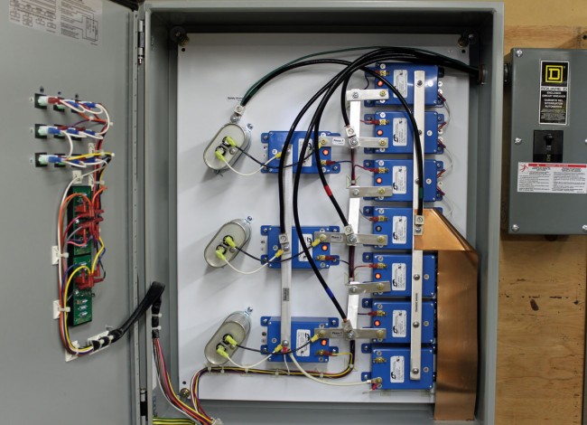
A better method of transient protection is the Series Surge Suppressor. These units are installed in line with the incoming service and include an inductor to add the required series resistance coupled with MOVs and capacitors. Most series surge suppressors also filter out harmonics and RF by design, something desirable, particularly at a transmitter site. Series surge suppressors look like this:
LEA DYNA systems series surge protector
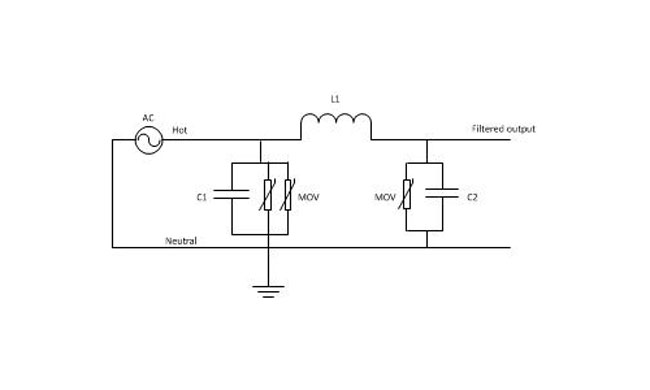
This is an LEA three-phase 240-volt unit. As in the other example, all phases have MOVs to neutral and each other. There are MOVs and capacitors on the line and load side of this unit (the line side is the bottom of the inductor). A basic schematic looks like this:
Series surge suppressor basic schematic
A few things to note; MOVs have a short circuit failure mode and must be fused to protect the incoming line from shorts to the ground. MOVs also deteriorate with age, the more they fire, the lower the breakdown voltage becomes. Eventually, they will begin to conduct current at all times and heat up, thus they should also be thermally fused. MOVs that are not properly protected from overcurrent or over-temperature conditions have the alarming capacity to explode and/or catch on fire. From experience, this is something to be avoided. Matched MOVs can be paralleled to increase current handling capacity.
The inductor is in the 100 µH range, which adds almost no inductive reactance at 60 Hz. However, it becomes more resistive as the frequency goes up. Most transients, especially lightning, happen at many times the 60 Hz fundamental frequency used in power distribution (50 Hz elsewhere unless airborne, then it may be 400 Hz).
Capacitors are in the 1-10 mF range and rated for 1 KV or greater as a safety factor. The net effect of adding capacitance is to create a low-pass filter. Hypothetically speaking, of course, playing around with the capacitance values may net a better lowpass filter. For example, at 100 uH and 5 mF, the cutoff frequency is 225 Hz, or below the fourth harmonic. Care must be taken not to affect or distort the 60 Hz waveform or all sorts of bad things will happen, especially to switching power supplies.
These units also need to have a bypass method installed. If one of the MOV modules needs to be replaced, power to the unit has to be secured. This can be done by connecting it to the AC mains before any generator transfer switch. That way, the main power can be secured and the site can run on generator power while the maintenance on the surge suppression unit is taking place.