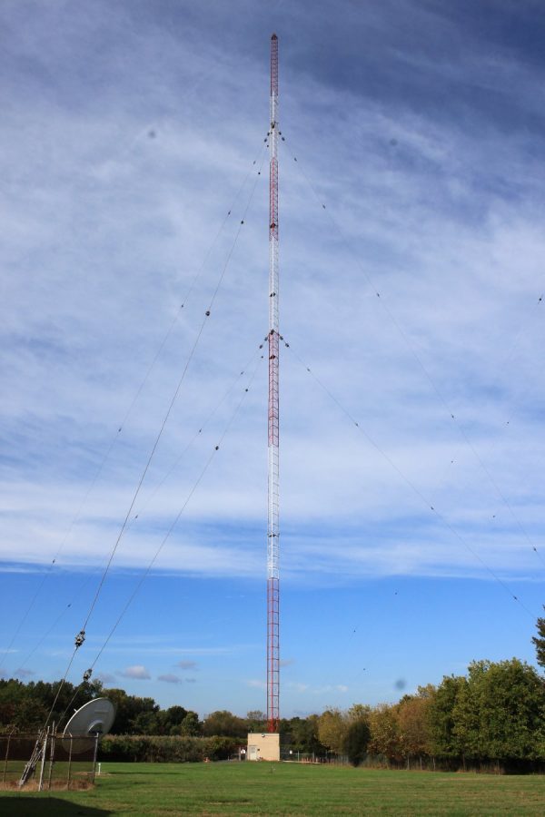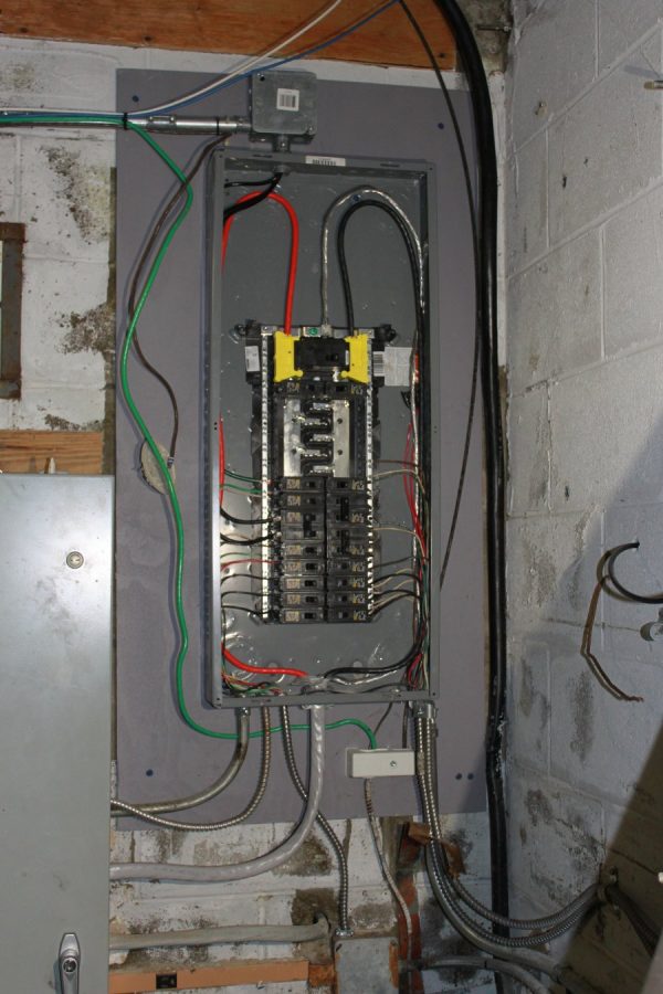
Recently, while working at a transmitter site built in the early 1940’s I noticed some fluorescent lights were out. Upon closer examination, I noticed that the bi-pin holder on one side of the bulb was damaged. This led to the removal of the fixture for repair, discovering these devices:
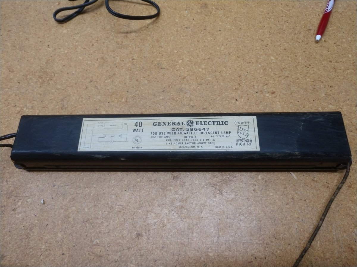
As this was made in Schenectady, NY, it is almost certainly original to the building. According to the EPA website, each one of these ballasts contains a capacitor with 3-4 ounces of PCB. There were 16 total fixtures, each with one ballast. The ballasts were removed and the fluorescent lamps were replaced with T8 120 Volt LED units. Any defective bi-pin lamp holders were replaced at the same time.
The danger posed by PCBs is minimal unless they leak or there is a fire. Partially burned PCB results in the production of dioxins, which are really bad. The old GE ballasts were properly disposed of.
The PCB capacitors and transformers were removed from the site many years ago. Other things that might have PCBs; are caulking and window glazing compounds.
That made me think; what else is around here? Several things came to mind.
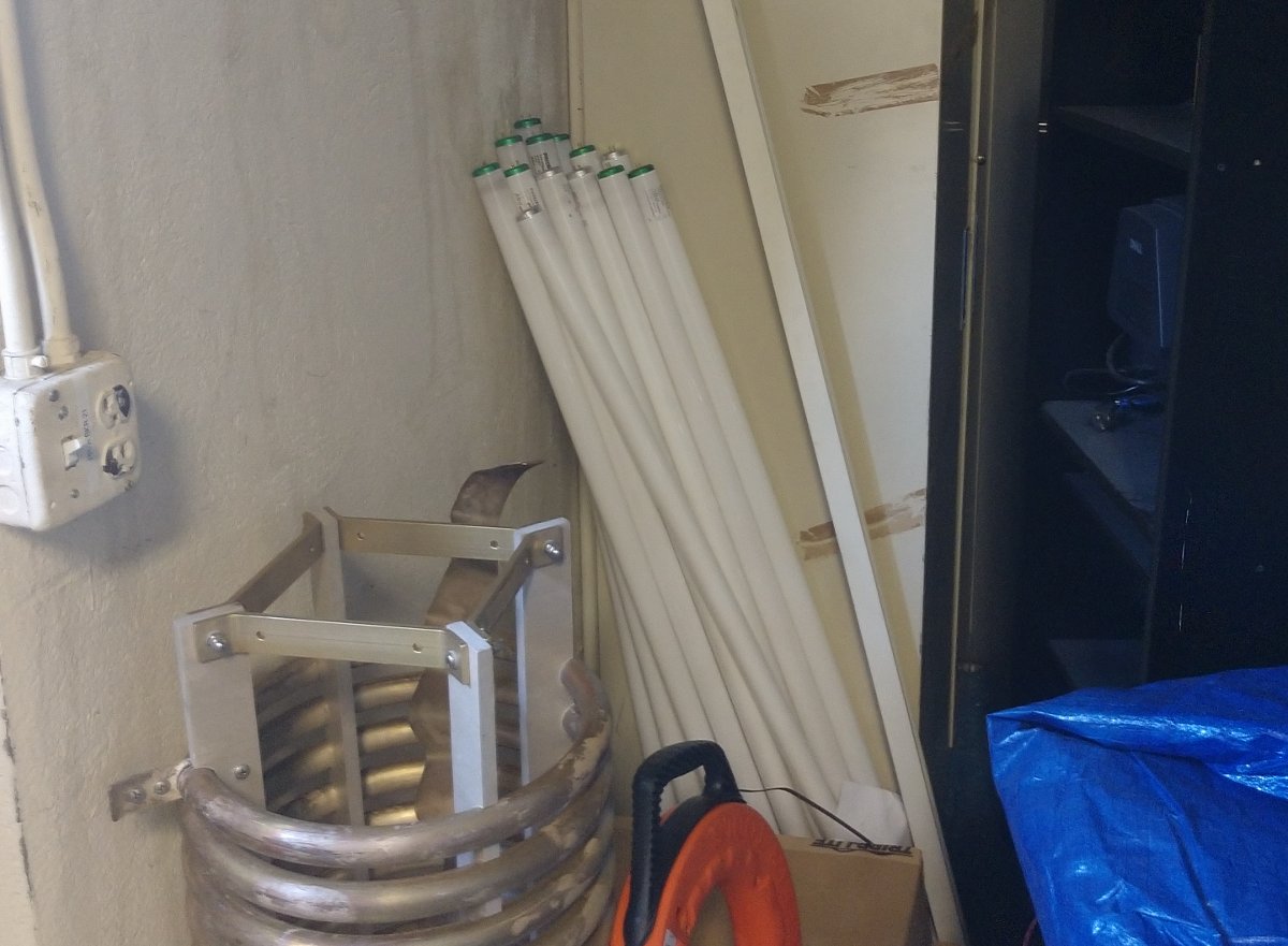
The fluorescent bulbs themselves contain a small amount of mercury. This is not a problem unless the bulb breaks. If the bulb does break, the EPA recommends leaving the room for 15-20 minutes. Then carefully clean up the broken glass and place it in a plastic bag. Smaller particles can be cleaned up with the sticky side of masking tape or duct tape. Do not use a regular vacuum to clean up the broken glass, this will spray mercury around the room.
The fluorescent bulbs should be disposed of as hazardous waste.
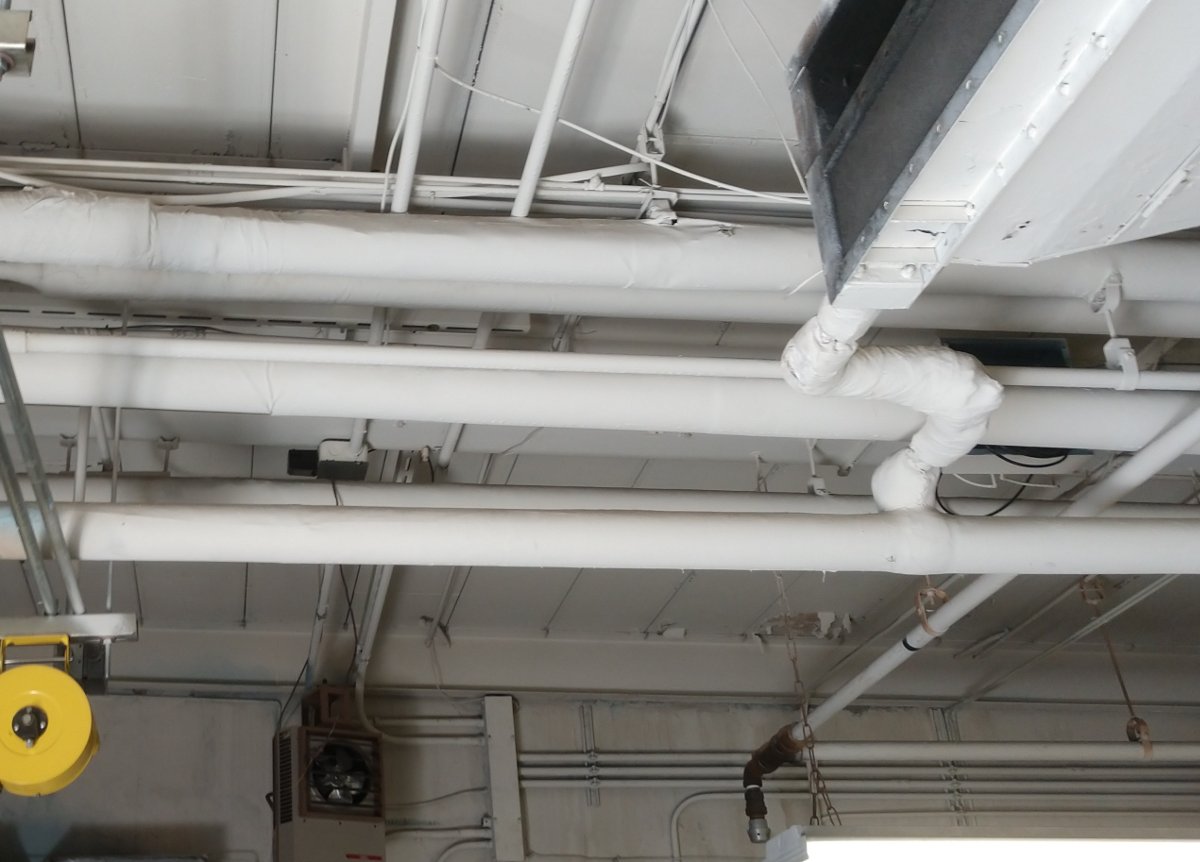
Asbestos lagging on the hot water/heating pipes. As long as the lagging is intact, there is no problem. All of the pipe lagging in this building is intact and in good shape. With asbestos, the problems start when things are disturbed. Any type of work on those pipes will require a mitigation plan. Something to keep in mind if there are any building modifications being planned.
If old-style pipe lagging like this is falling off or has been partially removed, it is best to have an asbestos survey done. Newer style lagging will be either closed cell foam, open cell foam, or fiberglass insulation with a cardboard cover.
Other things that can have asbestos are floor tiles and siding.
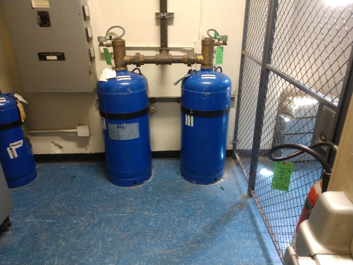
The halon fire suppression system can be hazardous if one is in the building when it discharges. Of course, fire itself is also a hazard. It is something to be aware of if the alarm goes off.
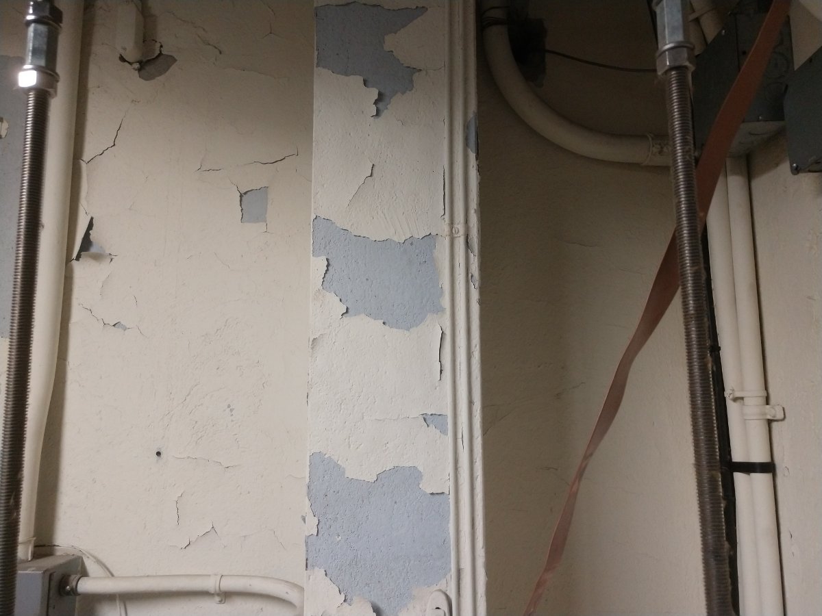
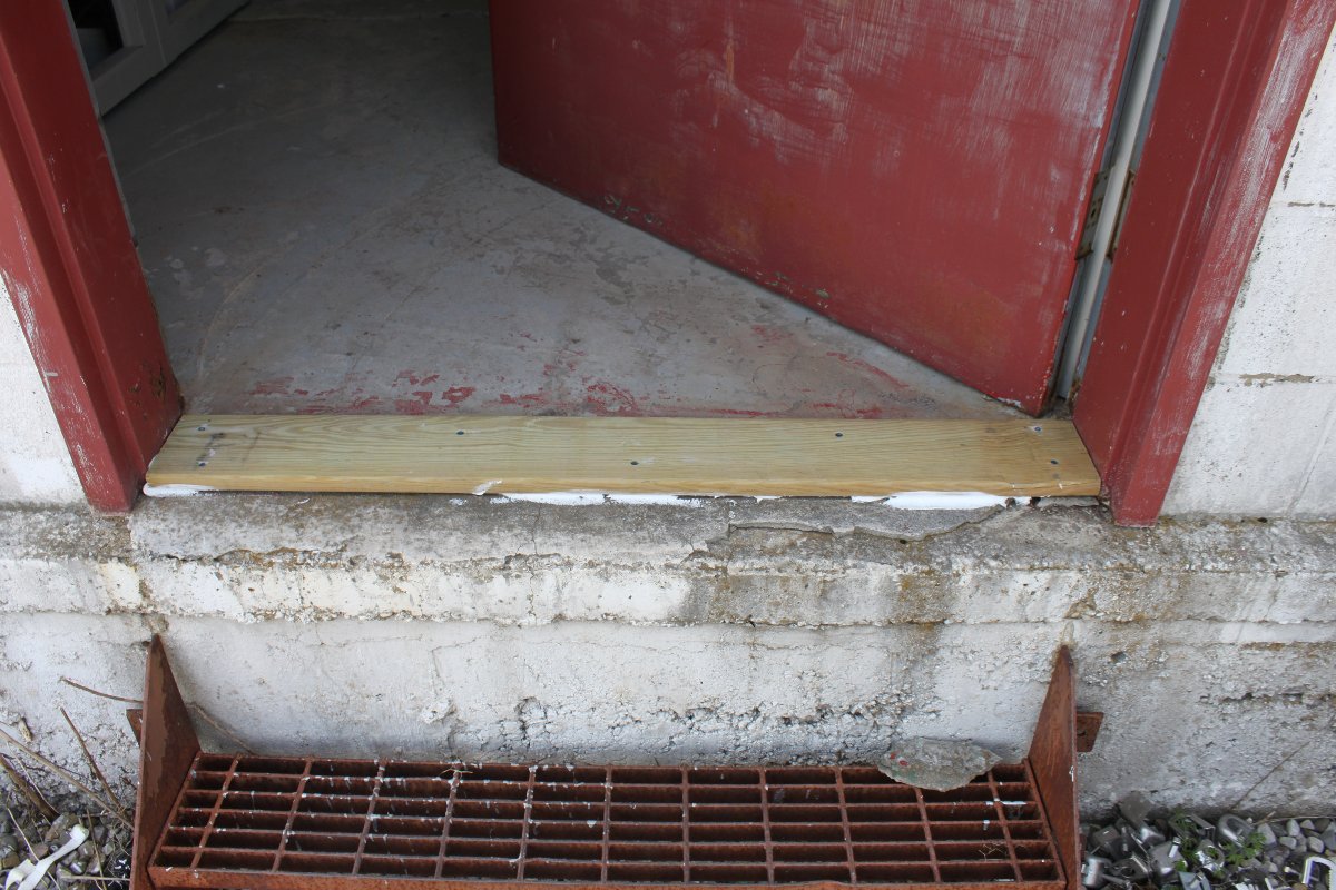
Since this building was constructed way before 1978, lead paint is likely on the walls. Not a huge problem unless it is chipping off and you accidentally eat the lead paint chips or inhale pulverized lead paint dust. To clean these up, use a vacuum cleaner with a HEPA filter. Alternatively, wear a HEPA filter and use a dustpan and brush. Do not use a regular vacuum cleaner.
If building modification work is being done in areas that may contain lead paint, a properly certified lead paint mitigation contractor should be hired to remove the hazardous material.
None of these situations pose a direct safety threat, however, one should be aware of these potential issues in their work environment.