As promised, here is the AM transmitter site maintenance checklist. This is for a generic directional AM station with a backup transmitter, generator, and an RF STL.
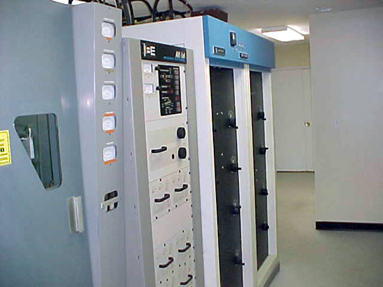
Broadcast Electronics AM6A transmitter
Usual disclaimers apply.
AM site Maintenance checklist
Weekly Maintenance:
A. Visit site, Check following:
Check critical transmitter values against last logged value
Check forward/reflected power on main transmitter
Check and reset any overloads
Check signal strength on STL against last logged value
Check generator fuel level
General check of building, look in all rooms, inspect for damage from vandalism, Leaking roofs, obvious signs of trouble, take steps to correct.
Monthly Maintenance:
B. Visit site, Check following:
Do a full multi-meter log, (includes tower phase angles, loop currents), run backup transmitter into dummy load.
Start and run generator for 5 minutes, check block heater, hoses, belts, oil and antifreeze levels
Calibrate remote control meters with transmitter meters, log it*
Check all tower fences for integrity and locked gates*
Complete Items 3, 4 and 5 under weekly maintenance.
Quarterly Maintenance:
C. Visit site, Check following:
Complete 1 through 5 under monthly maintenance.
Check all air filters, clean or replace as needed.
Check frequencies of all transmitters, STL receiver, and log.
Complete quarterly tower lighting and painting inspection*
Bi-yearly Maintenance:
D. Visit site, Check Following:
Complete 1 through 5 under quarterly maintenance.
Conduct monitor point readings for all directional antenna patterns*
Check base current readings for day/night towers. Ratio.*
Clean backup transmitter
Place backup transmitter on air and clean main transmitter.
Yearly Maintenance:
E. Check all licenses and authorizations for accuracy. Make sure that all renewal cards etc are in public file and are posted at control point.*
I read through the news coverage of the vandalism at the KRKO transmitter site. Apparently, there is some group of idiots people running around insisting that radio towers are bad for the environment and people’s health. These are the same ones who have torched SUVs and burned high-end housing developments down. Naturally, no pollution is released into the environment during these acts, or else they would be hypocrites.
They make these claims with no merit or scientific basis, instead relying on base fears to make people go crazy, either temporarily or permanently like. It is actually a pretty good motivator as both political parties and all sorts of fringe truthier, birthier, and others have discovered. If enough people insist that it is true, then it must be so.
Unfortunately, there is always some idiot around who thinks it is his or her duty to take action, to protect the rest of us from some terrible fate.
In the meantime, some security cameras at the transmitter site might be a good investment. Chances are, these Earth Liberators that sneak around with bolt cutters and hack saws will likely think twice if there is any chance of themselves going to jail.
By the way, those KRKO towers looked like self-supporters which would have been very difficult to get down. Did they rent that excavator, or was some construction equipment left unattended?
File under: Why we check the tower lights every day (or have an automated tower light reporting system):
56 years ago, on September 16, 1953 American Airlines flight 723 flew between the center and northeast towers of the WPTR antenna system while attempting to land at Albany County Airport. The plane crashed about 3/10 mile away near NY route 5 (Central Avenue) killing all 28 persons on board. To date, this is the worst aviation accident in the Albany, NY area.
Several years ago while cleaning out different AM transmitter site, I found a bunch of files about this accident in the trash bin. It seems that some engineer had moved a file cabinet during the great consolidation of the 1990s to the wrong transmitter site. In any case, I rescued the file and for your reading pleasure, have scanned the following documents:
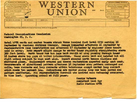
Original telegram to FCC in Washington DC regarding tower/aircraft colision
Retel WPTR north and center towers struck three hundred foot level 0930 morning 16 September by American Airlines Convair. Damage inspected afternoon 16 September by representative Zane Construction and afternoon 17 September by engineer Ideco tower used in array. Both report slight damage to center tower requiring straightening above 300 foot level. North tower has two legs bent result of wing passing through tower 18 inches above top guys at bolt intersection. Tower above bent and twisted but all right unless subject to high east wind. Impact sheered north beacon clevises and shattered glass. Replacement ordered and beacon restoration expected early next week. Measurements of directional pattern afternoon 16 September show pattern unchanged and nulls, base currents and loop currents within tolerances except center loop current which reads ten percent low. Indications are center pickup loop has been jarred and pattern unaffected. FCC representative Turnbull who arrived noon Wednesday concurred. No time lost. Operating at full power
George Wetmore, Assistant Genl Mgr, Radio Station WPTR
This is the statement of the transmitter engineer on duty at the time of the crash.
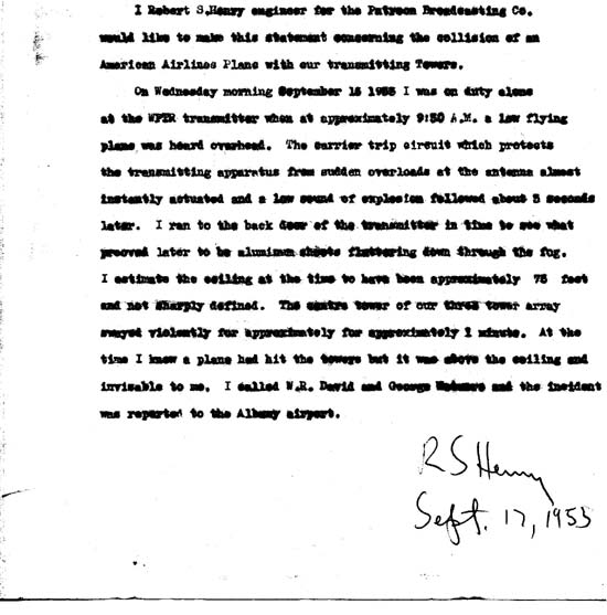
Statement from the Engineer on duty at the transmitter site
I, Robert S. Henry engineer for Patroon Broadcasting Co. would like to make this statement concerning the collision of an American Airlines Plane with our transmitting towers.
On Wednesday morning September 16, 1953 I was on duty alone at the WPTR transmitter when at approximately 9:30 A.M. a low flying plane was heard overhead. The carrier trip circuit which protects the transmitting apparatus from sudden overloads at the antenna almost instantly actuated and a low sound of explosion followed about 3 seconds later. I ran to the back door of the transmitter in time to see what proved later to be aluminum sheets fluttering down through the fog. I estimate the ceiling at the time to have been approximately 75 feet and not sharply defined. The centre (sic) tower of our three tower array swayed violently for approximately for approximately (sic) 1 minute. At the time I knew a plane had hit the tower but it was above the ceiling and invisable to me. I called W. R. David and George Wetmore and the incident was reported to the Albany airport.
Back in these days, the studios were located at the Hendrick Hudson Hotel in Troy, the transmitter site was manned by a licensed transmitter engineer whenever the station was on the air.
What is amazing is that the IDECO towers remained standing after being struck by Convair 240, a pretty good-sized aircraft.
American Airlines’ Flight 723 was a scheduled flight between Boston, and Chicago, with intermediate stops among which were Hartford (BDL), and Albany (ALB). The CV-240 arrived at Bradley Field at 06:57. Weather at the next stop, Albany, at this time was below the company’s landing minimums, but was forecast to improve to within limits by the time the flight arrived there. Departure from Bradley Field was made at 07:14. Because of poor visibility at Albany, several aircraft were in a holding pattern. The special Albany weather report issued at 07:50 indicated thin obscurement, ceiling estimated 4,000, overcast, fog, visibility 3/4 miles. Two aircraft left the holding pattern, attempted to land, but both executed a missed approach procedure. A third airplane landed at 08:16 following an instrument approach to runway 19. Immediately following this landing, Flight 723 was cleared to make an instrument approach to runway 19. Three minutes later the flight advised the tower that its approach was being abandoned because the aircraft’s flaps could not be lowered. At 08:30 Albany Tower reported:”All aircraft holding Albany. It now appears to be pretty good for a contact approach from the west. It looks much better than to the north.” Flight 723 was then cleared for a contact approach to runway 10. On finals for runway 10, the Convair descended too low. The right wing of the aircraft struck the center tower of three radio towers at a point 308 feet above the ground. The left wing then struck the east tower. Seven feet of the outer panel of the right wing including the right aileron and control mechanism from the center hinge outboard together with 15 feet of the left outer wing panel and aileron separated from the aircraft at this time. Following the collision with the towers, ground impact occurred a distance of 1,590 feet beyond the tower last struck. First ground contact was made simultaneously by the nose and the left wing with the aircraft partially inverted. The weather reported at the time of the accident was thin scattered clouds at, 500 feet, ceiling estimated 4500 feet, broken clouds, visibility 1-1/2 miles, fog.
PROBABLE CAUSE: “During the execution of a contact approach, and while manoeuvring for alignment with the runway to be used, descent was made to an altitude below obstructions partially obscured by fog in a local area of restricted visibility.”
The above reports notes that the aircraft traveled 1590 feet and struck the ground partially inverted. I do not know what the flaps-up landing speed of a Convair CV-240 is but the cruising speed is 280 MPH. It would be safe to say the aircraft was traveling in the 120 to 130 MPH range or about 220 feet per second. At that speed, it was likely airborne for about 7 seconds after it hit the tower. Enough time to look out the window, realize what was happening, and say “Oh, Shit!”
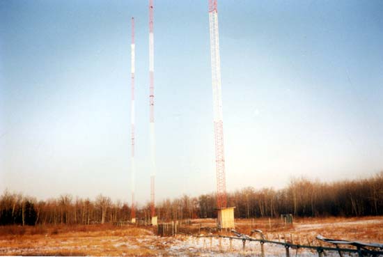
IDECO towers WDCD antenna system, the northeast tower is farthest
IDECO stood for the Internation Derrick Company, they build cranes, derricks, and bridges as well as radio towers. Apparently, they made pretty good stuff because those same towers are still standing today.
Not that checking the tower lights would have averted disaster in this case, it appears to be pilot error compounded by bad weather that caused this incident. But there have been more recent aircraft/radio tower accidents, some of which have involved possible faulty tower lights. I wouldn’t want that on my conscience.
This is one of my favorite old transmitter memories. Back when I landed my first Chief job, I was working for an AM/FM combo. The AM station was a 50,000-watt flame thrower that first went on the air in 1947. The original transmitter, a General Electric BT-25-A was still in service as a backup unit. These pictures are from the last night it operated, December 16, 1993. The bank made us remove all of the PCB transformers and capacitors before they would refinance their loan. Of course that was most of the transmitter, the rest of it was scraped or sold for parts.
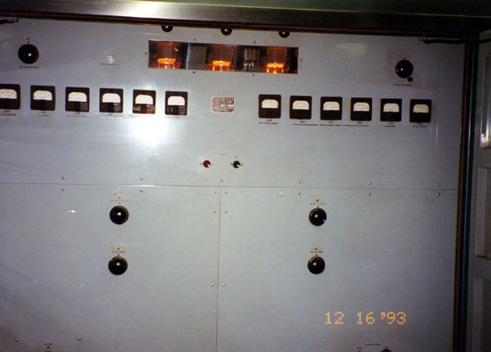
This is a long transmitter, GE BT-25-A looking from the control cabinet
The transmitter takes up the entire span of the room. There were eight large cabinets, each with its own stage or section. The stages were connected to each other by a wiring trough in the floor. The transmitter used lead-jacketed cable within and between sections.
IPA stage with “multi-meters”
The IPA section had been modified to use 833A tubes. This is where the RF was developed and amplified for the final section. It is in the middle cabinets of the transmitter, the audio and control section being to the left, the PA and PA power supply being to the right.
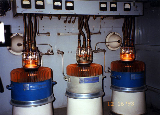
PA section. Those are WL 5891 tubes.
Final section. There were three tubes, only two were in use at any given time. The third tube was a spare which could be quickly placed in service by throwing a knife switch and moving those bars on the back wall around. This picture was taken with filament voltage only, we had to close the door to turn on the PA voltage.
air cooling blower
The transmitter was cooled by this blower which faces down into the floor. Concrete duct work carried the air to the various stages of the transmitter. The blower is powered by a 2 1/2 HP motor. There were two blowers, one in use and one in standby. Behind this is an air mixing room and filter room. During the winter time, the transmitter waste heat was used to heat the building by closing a series of ducts and opening other ones.
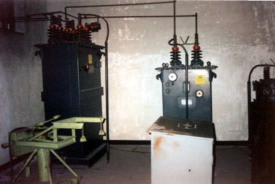
Modulation transformer and modulation reactor
This is in the transformer vault. The unit to the left is a modulation transformer, it was 7 feet tall. Directly in front is the modulation reactor and just out of the picture to the right is the plate transformers. The plate supply was 480 volts 3 phase. The other piece of green equipment is a hydraulic tube jack, to get the 5891 final and PA tubes out of their sockets.
The transformers were what contained most of the PCBs. The modulation transformer contained about 150 gallons of Pyranol, the GE trade name for their transformer oil. Pyranol contained greater than 750,000 parts per million PCB.
It is a shame we had to kill this transmitter, it sounded wonderful on the air. The day we signed it off, there was nothing like it, not the Mw-50B that replaced it, nor the Nautel ND-50 that replaced the MW-50, nor the DX-50 at the competing station across town.