WKIP; tune up on shorter tower

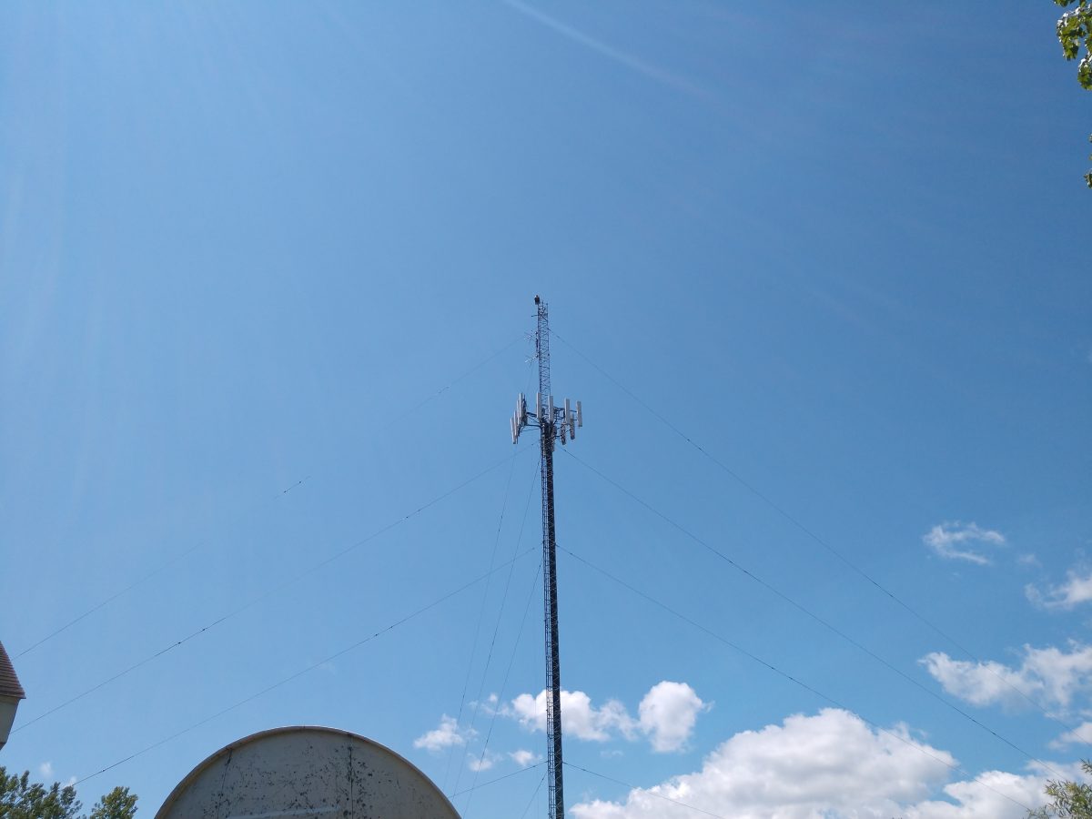
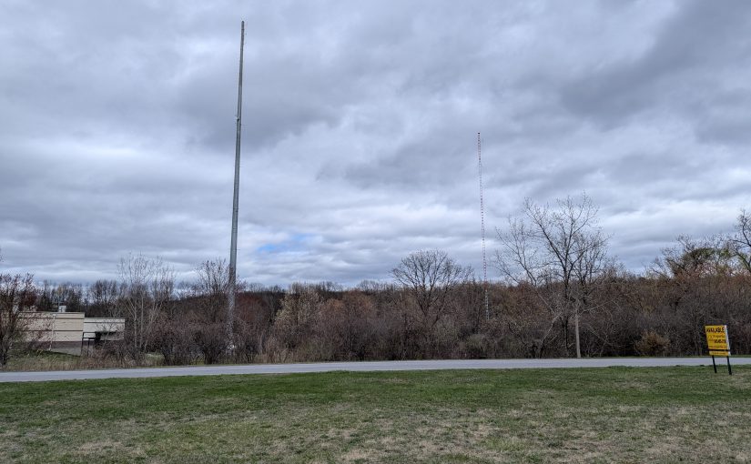
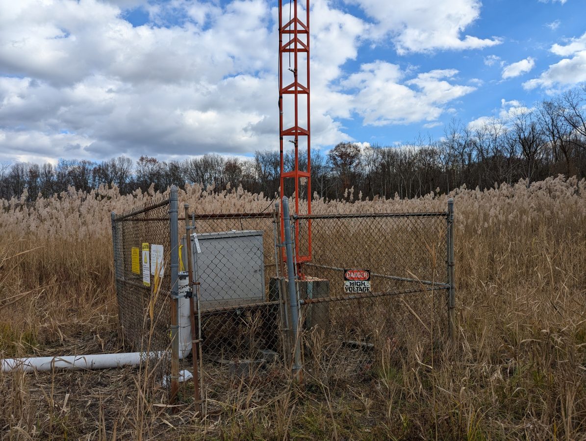
This tower was previously part of a two tower DA. The taller tower was taken down and slowly replaced with a monopole to facilitate vertical real estate development. The shorter tower was retained as the radiator for WKIP-AM, 1,450 kHz, Poughkeepsie, NY.

WKIP tower


Knowing that the tower is 85 degrees at 1,450,000 Hz, I calculated the height above the base insulator to be 48.816 meters. The tower face is two feet or 0.6096 meters (this becomes important). Using the chart, we can see that the theoretical resistance should be about 25 – 30 ohms:

Height over width, antenna resistance


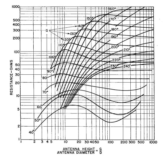
The bottom or X axis on this graph is the ratio of the antenna height over the antenna diameter or 48.816/0.6096 meters or 80.

The reactance is slightly less clear according to this chart:

Height over width, antenna reactance


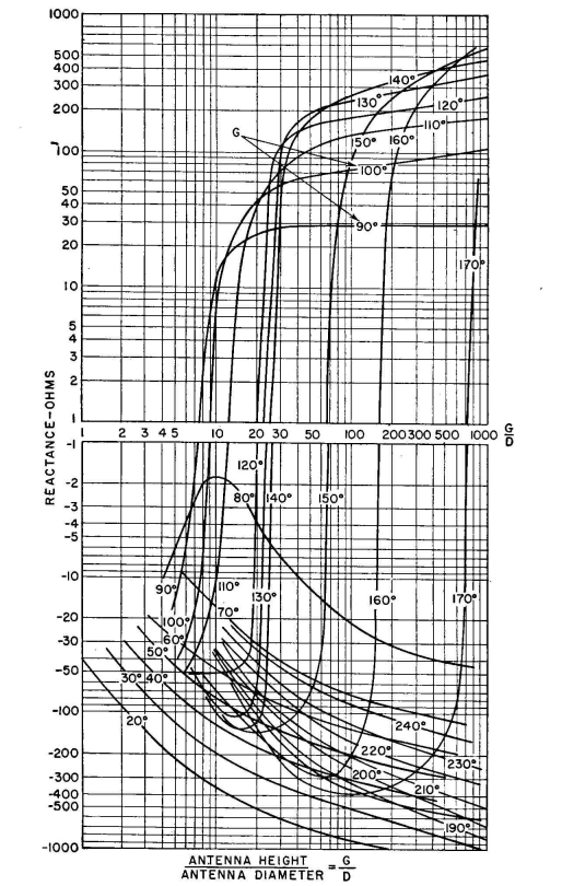
Between 80 and 90 degrees, a large phase shift occurs due to resonance. That means the reactance could be either negative or positive, but will likely be a low number, say +/- 5 ohms. That may be why this height was chosen for the second tower in this system.

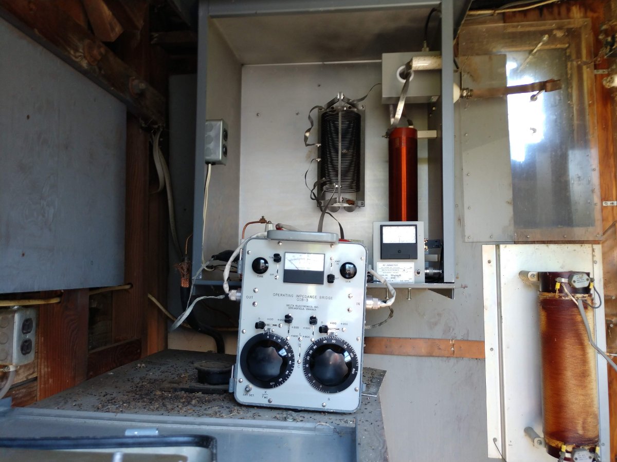
And now for a bit of reality; all of that theoretical information is nice, but a measurement under power is where the rubber meets the road. Using the trusty OIB-3, I obtained a reading of 48 ohms base resistance and +j 37.6 reactance. Thus the base current should be 4.56 amps at 1,000 watts.

OIB-3 base impedance measurement

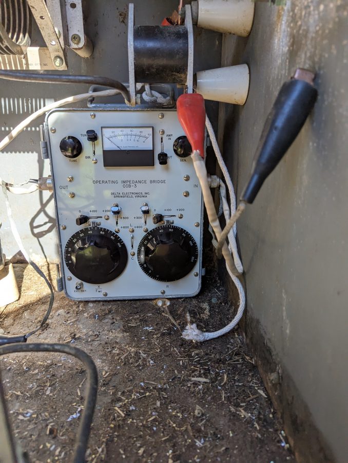
It was a little tricky setting up the OIB-3. The only place for it was far back in the ATU meaning I had to be careful reaching around active components while getting a reading. That being said, it is only 1,000 watts and in the end, no new RF burns were acquired.

Delta base current meter

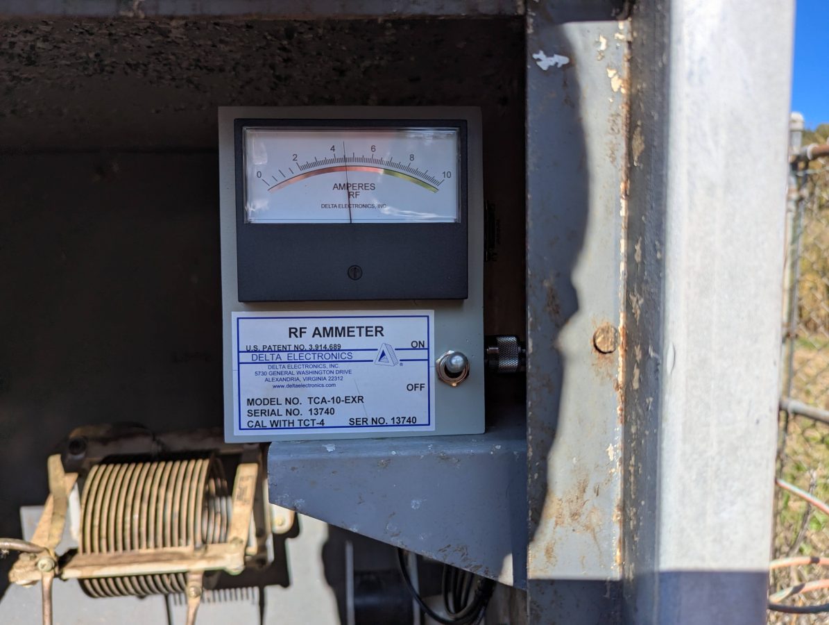
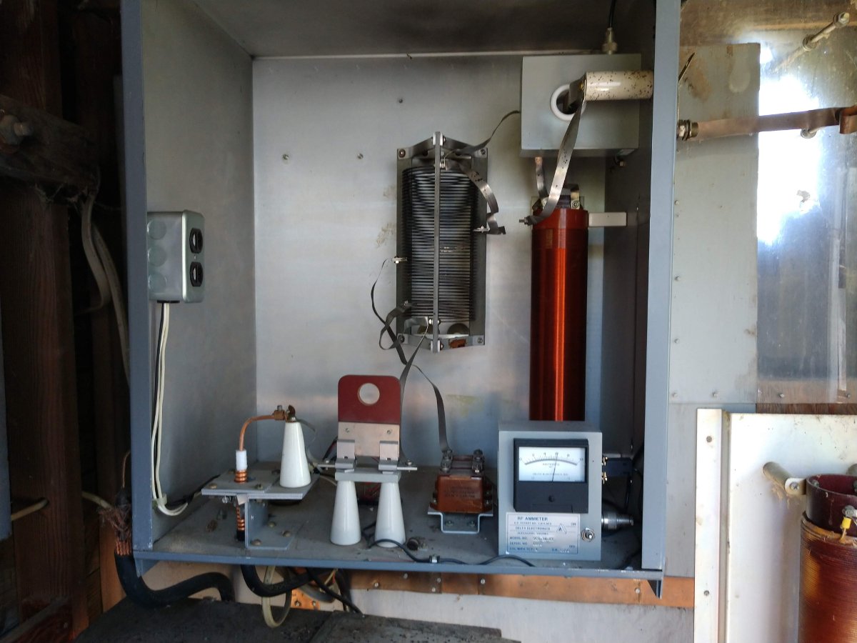
The new Delta Electronics base current meter confirms the measured base resistance with the use of Ohm’s Law; I = √(P/R).
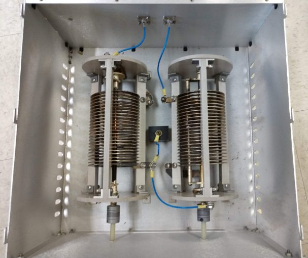
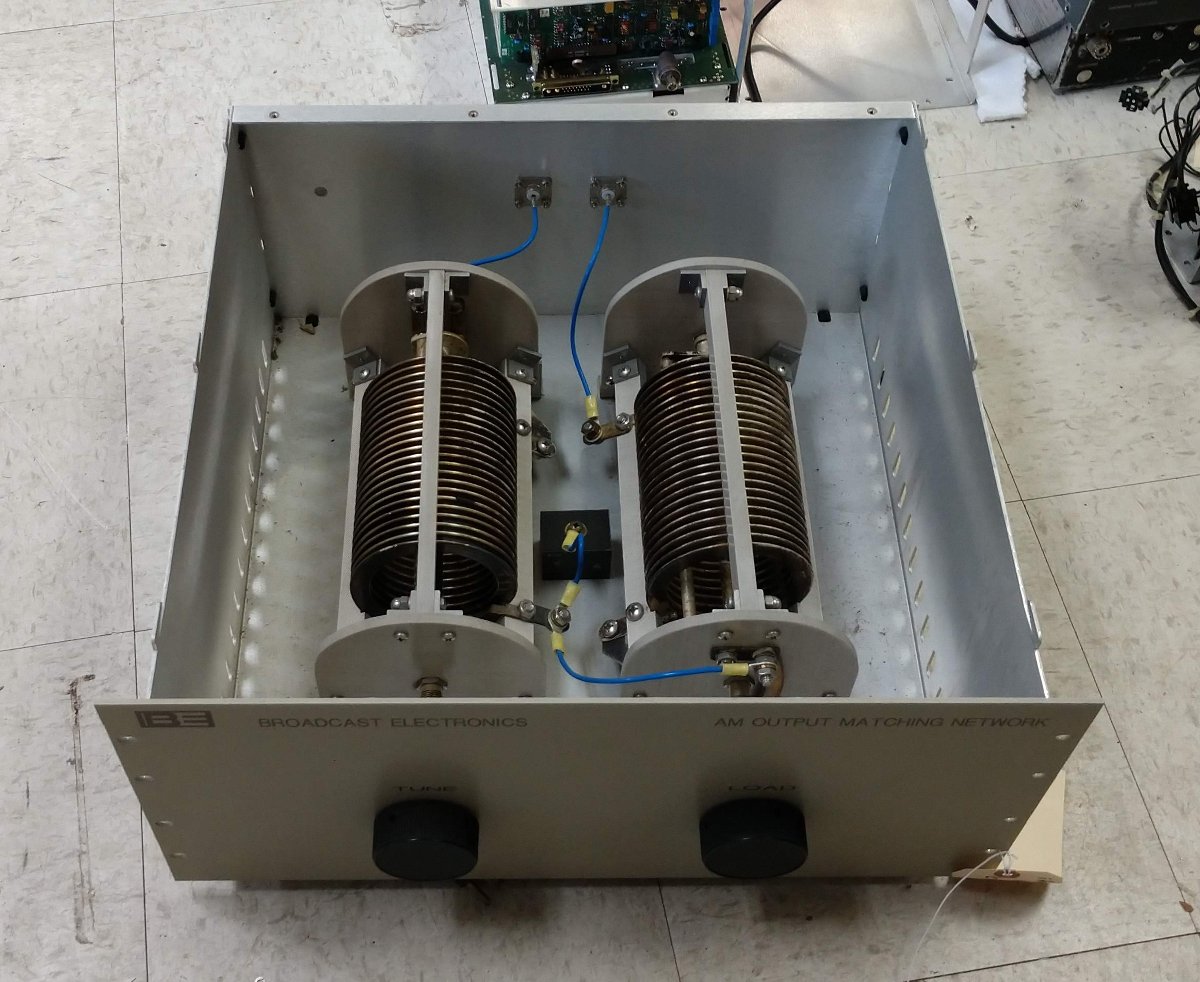
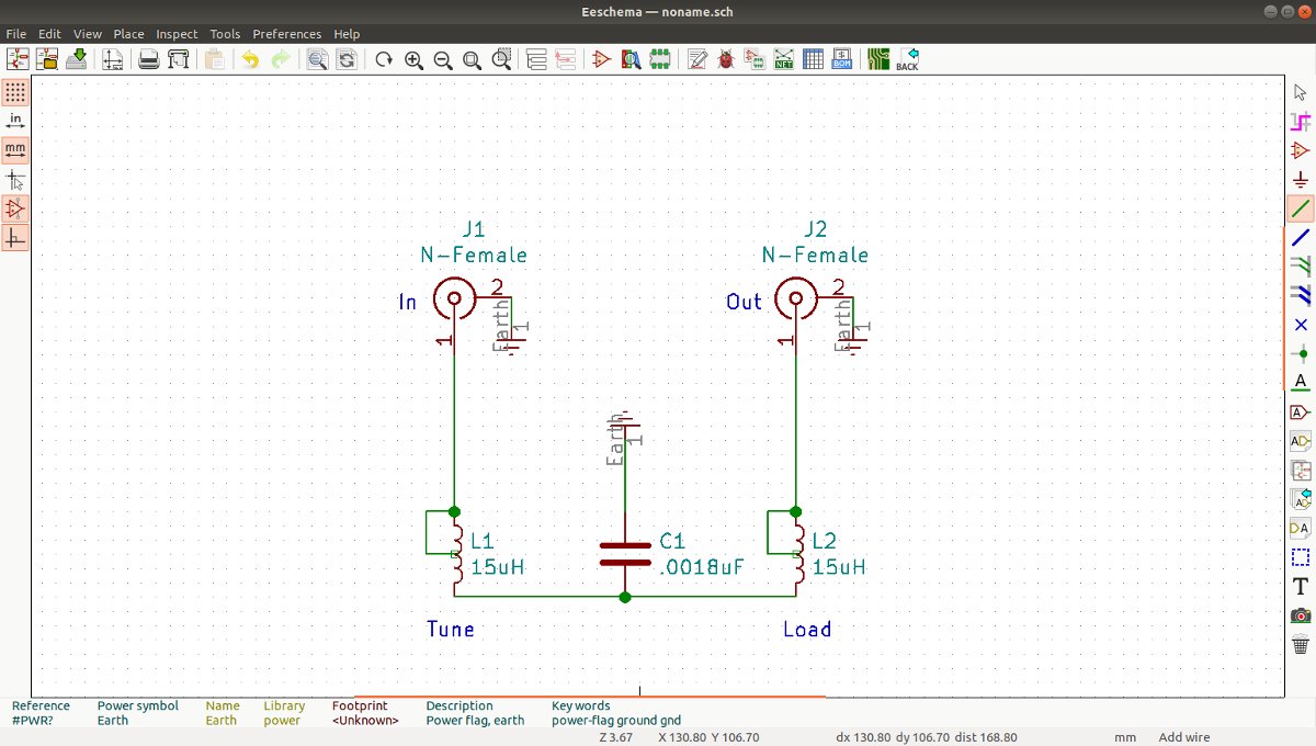
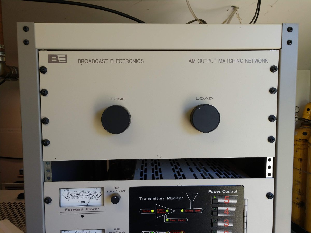
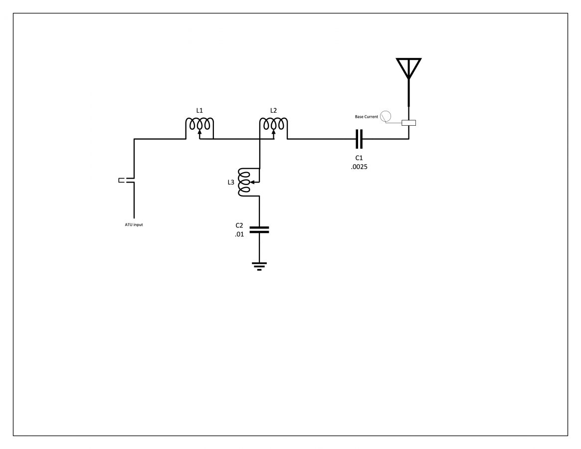
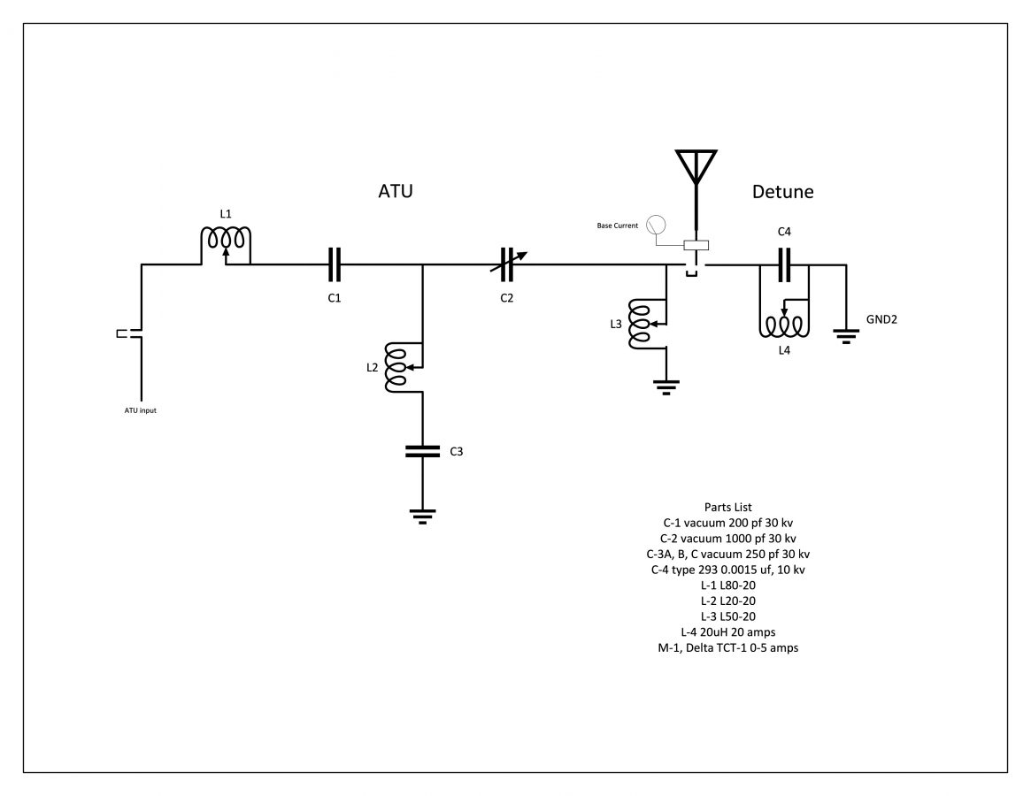
ATU for WKIP tower, circa 1960


This information is useful for checking the component ratings in the ATU. The series capacitor on the output leg needs to handle the full carrier current plus 125% modulation. I calculate that to be 10.125 amps, so the 12 amp capacitor is sufficient. The ATU is a standard T network with a capacitive leg to ground.

WKIP ATU Schematic

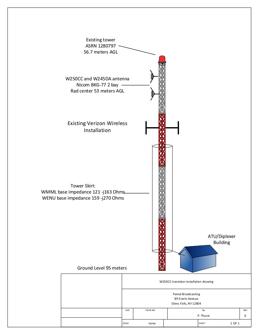
While construction was underway both taking down the old tower and putting up the new monopole, the base impedance of the radiator changed several times. Thus, we waited until all of the construction was completed and the monopole was detuned.

Mono Pole, constructed
Detuning skirt installed
ATU and detuning network for monopole

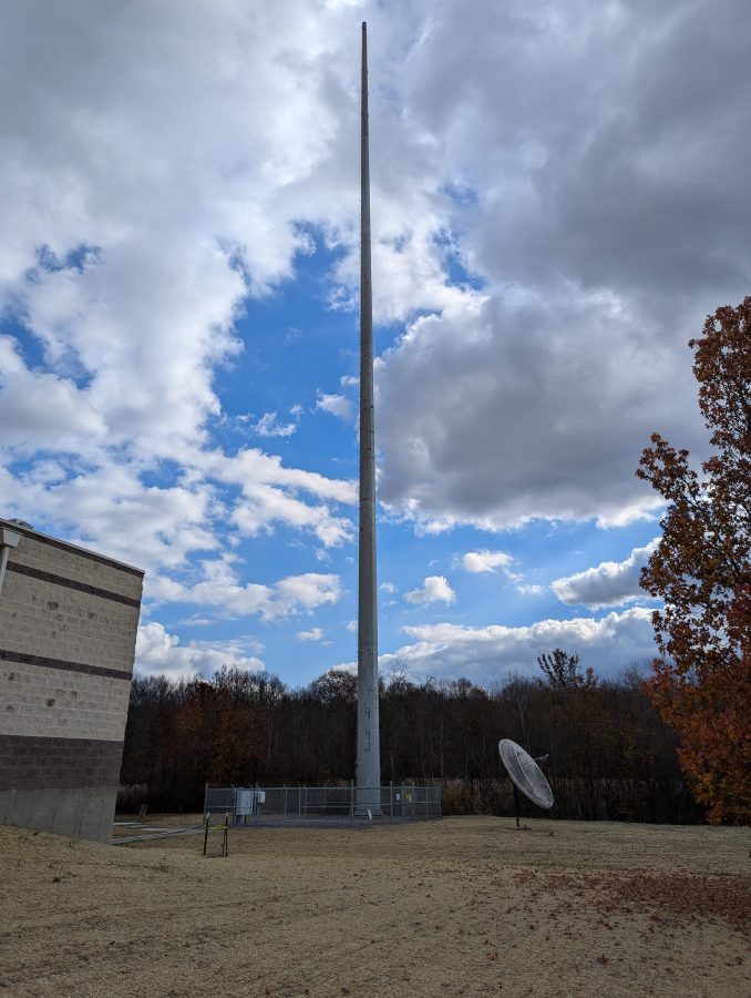
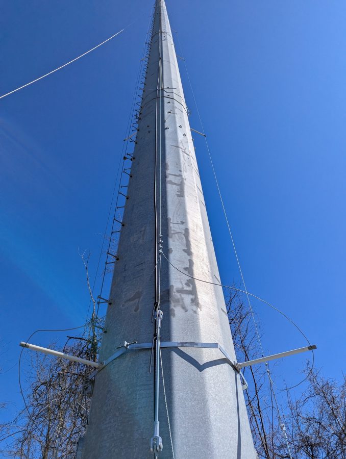
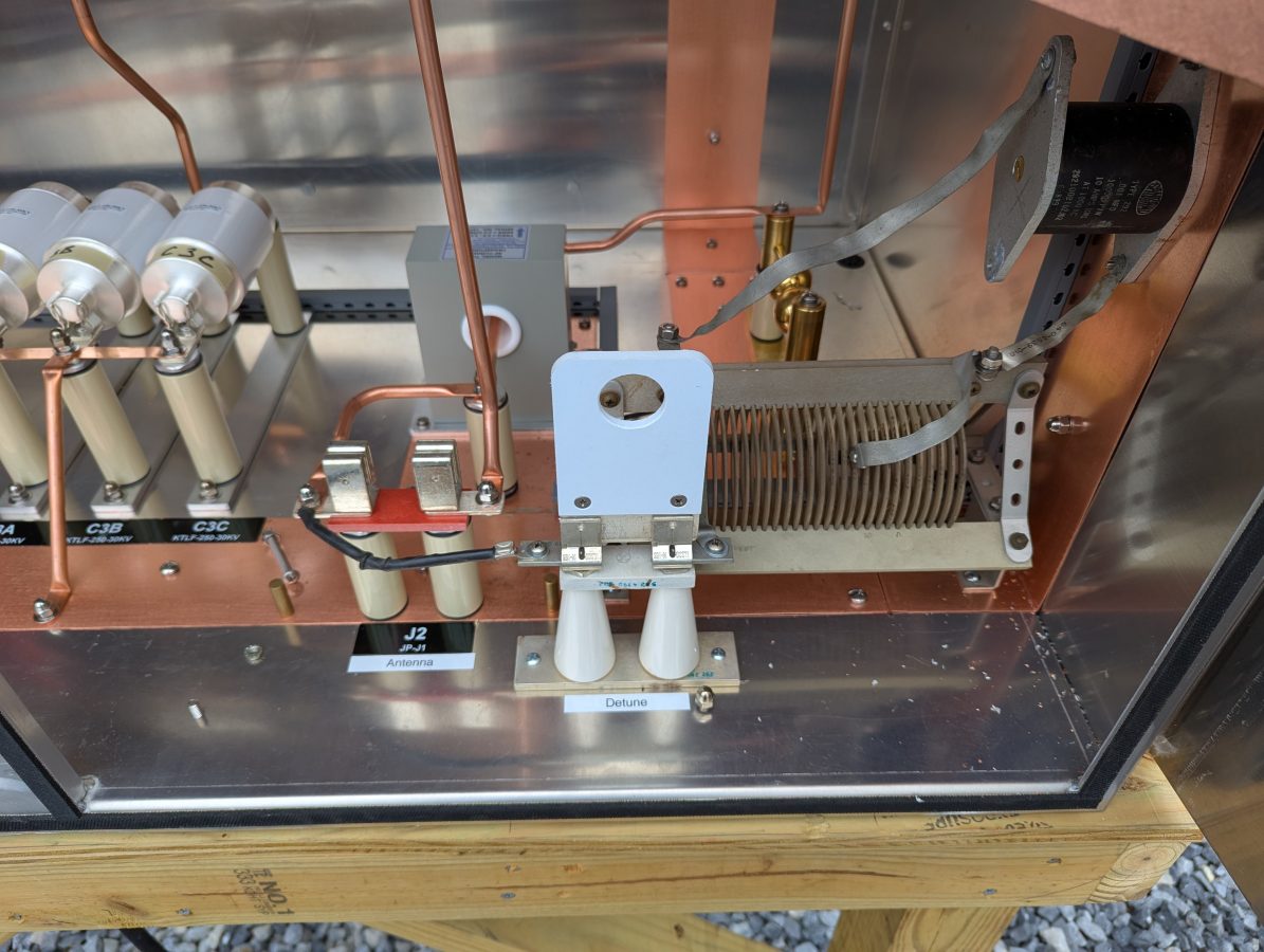
The skirt wires on the monopole are doing double duty. They are first, detuning for the AM tower located about 57 meters (186 feet) away. Next, they are a backup antenna system in case that main tower becomes unusable. This can happen from time to time as the swamp floods or if any type of tower work is needed. To do that I installed another J plug with the detuning network, which will be the normal position. To switch to antenna, it is moved to the antenna position. The base current meter is on the output leg, so it can be used to detune the monopole or measure the station output power.

Monopole in detune mode

I used the analyzer to get the detuning network close to resonant. The second step involved using the base current meter to touch up the tuning with the transmitter running into the tower 57 meters (186 feet) away. This is necessary because the two structures are close together. The skirt wires on the monopole pick up a lot of RF, therefore the stray capacitance on the inductor coil plays a role in the circuit. The net result is less inductance is needed when the transmitter is on. The resonance point will shift somewhat with ground conditions, but as long as the monopole impedance is high (above say 2K ohms) the structure should be invisible to the nearby 1,450 KHz radiator.

Monopole detuned for 1,450 kHz; impedance is 4.07 K ohms, at or close to resonance

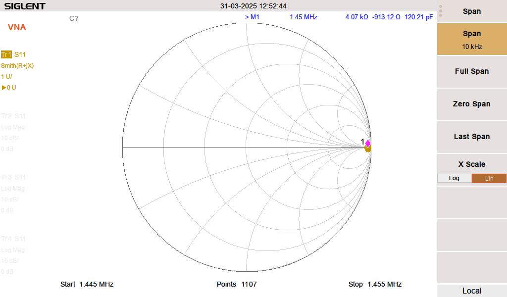
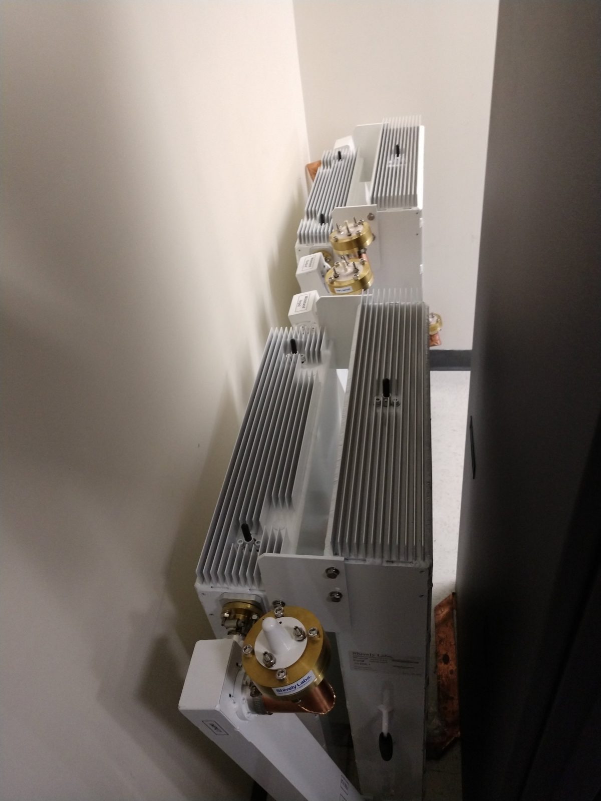
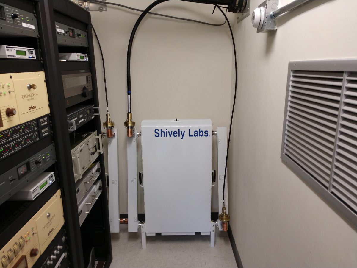
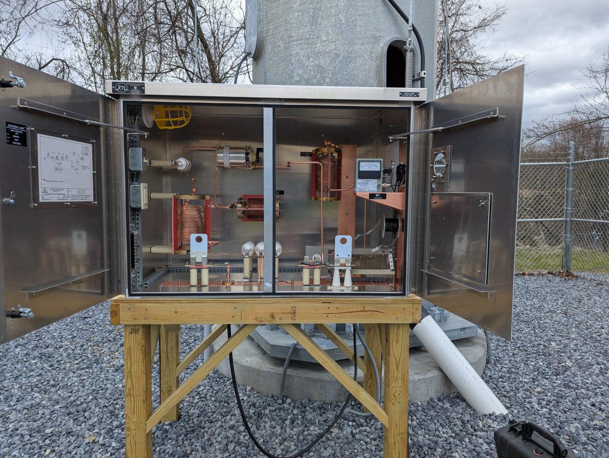
The ATU for the monopole looks like this:

The operating impedance measurement shows a 47 ohm impedance, making the daytime base current 4.61 amps. It is coincidental that the two tower impedances are that close.

Aux tower base current meter

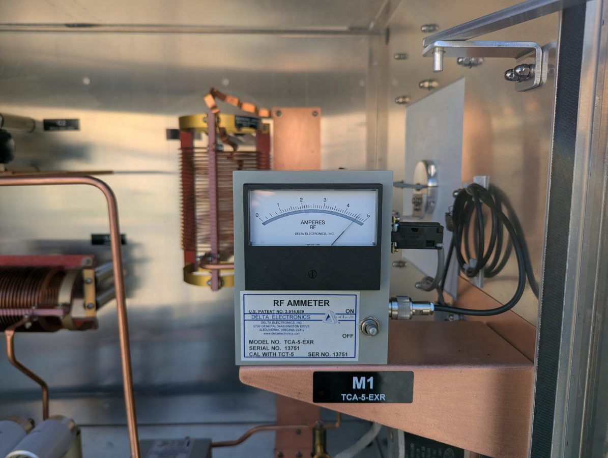
The new base current meter agrees with the impedance measurement.

BE AM tuning network

Occasional reader Scott asked for a picture of the inside of a BE AM output tuning network.  I figured it might be helpful to make a short post about it.

These things are pretty simple; a T network with a capacitive leg to ground.

BE AM Output tuning network

This particular unit is for 1230 KHz.  I believe the capacitor is frequency determined and they may also use larger inductors for lower frequencies.

BE AM output tuning network schematic

The inductors are Kintronic LV-15-20 (15uH 20 amp) and the capacitor is 0.0018 uF CDE 6KV 5.6 amp.

The issue with this particular unit is dirt.  The inductors have round metal plates that roll along the inductor coil to make the variable inductor tap.  Dirt has accumulated on the coil turns and on the inside of the plates.  This, in turn, causes arcing anytime the Tune or Load controls are moved.  A thorough cleaning should take care of the problem.

More AM retuning work

Working on another old AM station, this one is a simple Class C one tower on 1230 KHz.

Broadcast Electronics AM Output Tuning Network

The main problem today was this BE AM output network unit between the BE AM1A and the ATU.  This site has had some dirt difficulties over the years and the internal parts of this tuning unit arc at full power.  I attempted to drive the ATU directly with the transmitter, which was a no-go.

Gates Radio 1 KW AM ATU, circa 1947

I took a look at the ATU, which is a pretty standard Gates 1 KW ATU from the late forties or early fifties.  I have seen perhaps dozens of these things.

My first thought was that over the years, likely due to changes in the ground system, the base impedance has shifted away from its licensed values.  However, a quick measurement of the base impedance shows it to be exactly at the licensed value, 17.3 ohms.  The tower is 67 degrees tall so the impedance value is right in the theoretical norm.

I  measured the input to the ATU, which showed 38 ohms with about 7 ohms of capacitive reactance.  I can only surmise that it has always been this way.  The transmitter in use before the BE AM1A was a Harris/Gates Radio BC-1G.  That model transmitter will drive anything including an open transmission line.

Retuned ATU input; 49 ohms resistive, 0 ohms reactance

Having the bridge on hand, I decided to retune the ATU for a better match. I put the bridge on the input terminals of the ATU and set it to 50 j0.  Using the remote control, I turned the transmitter off and on while making small adjustments to the output strap on the coil until the resistance was 49 ohms with zero reactance.  I would have gotten it to 50 ohms, but the strap on the output side of the coil would not stretch far enough to reach the proper spot on the coil.

Now the transmitter will run into the ATU directly at full power with about three watts reflected.   The BE AM output matching network unit has been removed for cleaning and repairs.  I will reinstall it once those repairs are completed.

A tale of five signals

I am currently finishing an interesting project involving putting up two translators on a diplexed AM tower which also holds a mobile phone/data tenant as well.  All-in-all, this seems to be a very efficient use of vertical real estate.

WMML WENU tower, Glens Falls, NY

The AM stations are WMML and WENU in Glens Falls, NY.  The AM stations are diplexed using a Phasetek diplexor/ATU.

Diagram showing WENU/WMML tower with W250CC/W245DA antenna installed
Diplexor diagram, WENU/WMML Glens Falls, NY

The translators are W250CC and W245DA which are using a NICOM BKG-77/2 two bay 3/4 wave spaced antenna mounted at 53 meters AGL.  The translators use a Shively 2640-04/2 filter/diplexor which is a broadband input port in addition to the translator input ports.  Since these translator signals are only 1 MHz apart, the higher-power Shively filter was installed because it has better rejection characteristics.  The broadband input port allows the NICOM antenna to be used as a backup for any of the three FM stations; WKBE 107.1, WNYQ 101.7, or WFFG 100.3.  Two transmitter sites for those stations are mountaintop locations which are very difficult to get to in the wintertime.  Having a backup site available takes some of the pressure off during storms or other emergencies.

Shively 2640 -04/2 filter for W250CC and W245DA

The NICOM FM antenna was mounted on the tower when W250CC went on the air in October 2016.  When it was installed, the base impedances for both AM stations were measured.  For some reason, WENU 1410 KHz seems to be more sensitive to any changes on the tower, thus the WENU ATU needed a slight touch-up.  When working on diplexed AM systems, it is also important to make sure that both trap filters, which are parallel resonant LC circuits, are tuned for maximum rejection of the other signal.  During this particular installation, nothing was added to the tower and no change in the base impedance for either station was noted.

Shively Filter, connected to transmitters and antenna

As a condition of the construction permit, measurement of spurious emissions of all stations sharing the common antenna needed to be completed to ensure compliance with FCC 73.317(b) and 73.317(d).  I made careful measurements of the potential intermod products between the two translator frequencies.  This measurement was completed with my TTI PSA6005 spectrum analyzer.

The primary concern here is mixing products between the two transmitters. Both transmitters are BW TXT-600 with low pass filters before the output connector. There are three frequencies of interest;

  1. (F1 – F2) + F1 or (97.9 MHz – 96.9 MHz ) + 97.9 MHz = 98.9 MHz
  2. F2 – (F1 – F2) or 96.9 MHz – (97.9 MHz – 96.9 MHz) = 95.9 MHz
  3. F2 + F1 or 97.9 MHz + 96.9 MHz = 194.8 MHz

That, plus harmonic measurements out to seven or eight harmonics of the fundamental frequency should be enough to demonstrate compliance with FCC out-of-band emissions standards. Being that this site has LTE carriers, it is very important to measure the harmonics in those bands. Mobile data systems often use receiver pre-amps, which can amplify harmonics from the FM band and make them look out of compliance. Having a base set of readings to fall back on is always the best course in case the “out of tolerance” condition gets reported to the FCC.

Measurements on these frequencies must meet the emissions standards outlined in FCC 73.317 (d), which states:

Any emission appearing on a frequency removed from the carrier by more than 600 kHz must be attenuated at least 43 + 10 Log10 (Power, in watts) dB below the level of the unmodulated carrier, or 80 dB, whichever is the lesser attenuation.

Harmonic frequencies to be measured:

Harmonics for 96.9 MHz fundamentalHarmonics for 97.9 MHz fundamentalComments
193.8195.8 
290.7293.7 
387.6391.6 
484.5489.5 
581.4587.4 
678.3*685.3*US LTE Band 71
775.2*783.2*US LTE Band 5
872.1*881.1*US LTE Band 5
969.0979.0 

*Frequencies that fall within the mobile data LTE bands. Traces were recorded and saved for these frequencies.

All of that information, once compiled is attached to the FCC form 350-FM, which, once filed grants Program Test Authority.

BW TXT-600 V2 translator transmitters
BW TXT-600 V2 translator transmitters under test and measurement