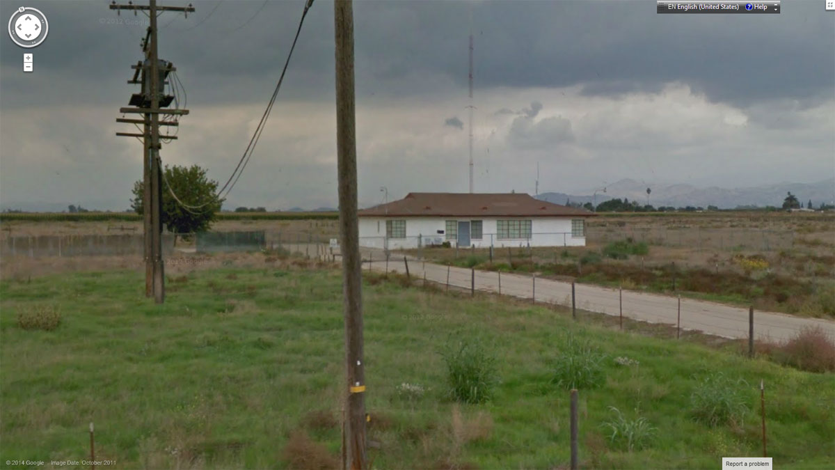
Update: Thank you, Jim. The mystery site is KFIG (formerly KFRE) in Fresno, CA. This is what the transmitter building looks like from the outside today:
KFIG transmitter, circa 2011
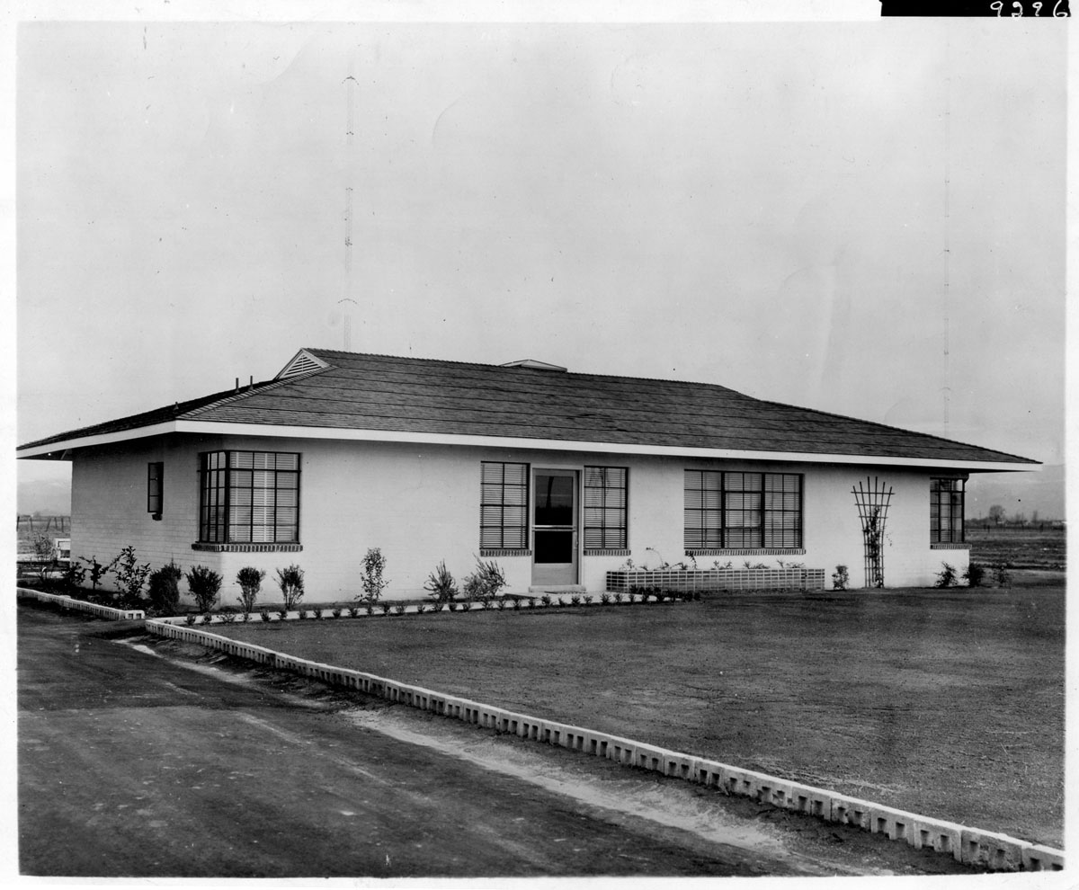
In the previously mentioned rescued file cabinet and along with the WFLY transmitter site construction information, I also found these interesting photographs:
Mystery AM transmitter site, plate 9296
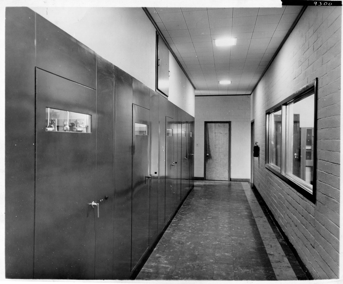
I do not know what transmitter site this is. From the photo, it has a two-tower (guyed) directional antenna. It looks to me to be somewhere out west. The transmitter is a General Electric BTA-25 or BT-25, the same as the former WPTR and WCKY transmitter. I know this back hallway well:
Mystery AM transmitter site, back hallway of GE BT-25. Plate 9300
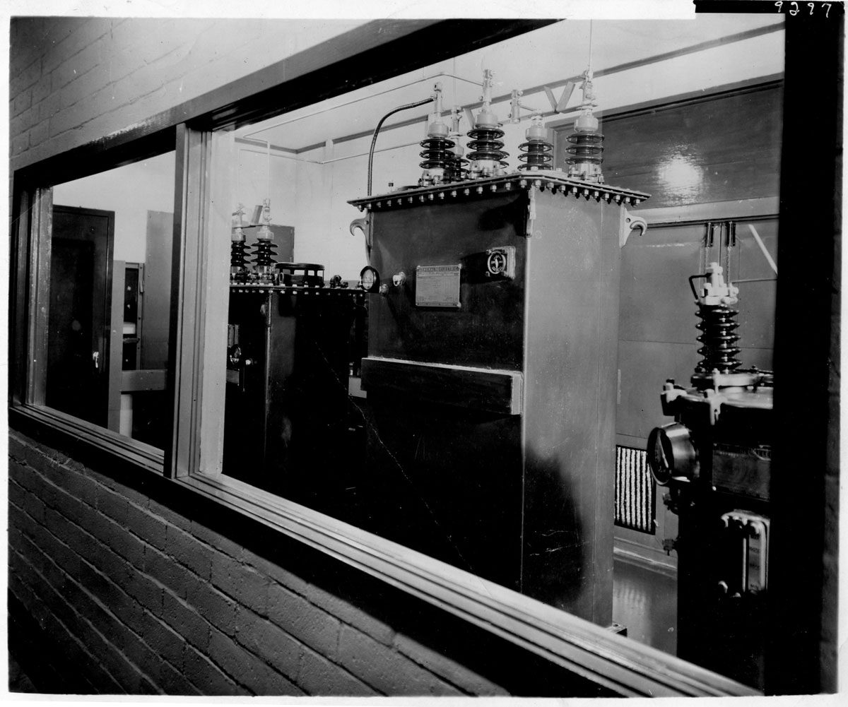
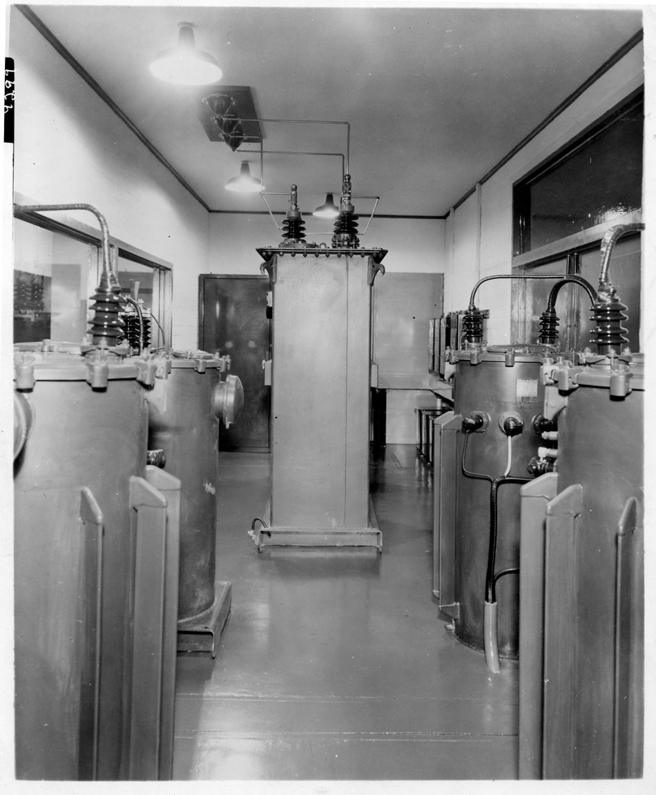
This is the transformer vault:
Mystery AM transmitter site, transformer vault. Plate 9297
Modulation transformer and three-pot plate transformer:
Mystery AM transmitter site, GE BT-25 modulation transformer. Plate 9299
I would say that these may be promotional photos, because of the spotlessly clean installation and the plate numbers on each print. Unfortunately, there are no pictures of the front of the transmitter, including the operator console.
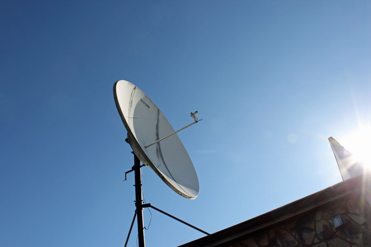
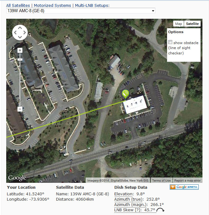
Periodic attention is required for most satellite receive-only earth stations. This particular dish sticks up above the roof line of a two-story building. It acts as a big sail and sometimes, after a particular wind event, it gets slightly off of its intended satellite, AMC-8.
Comtech 3.7 meter dish
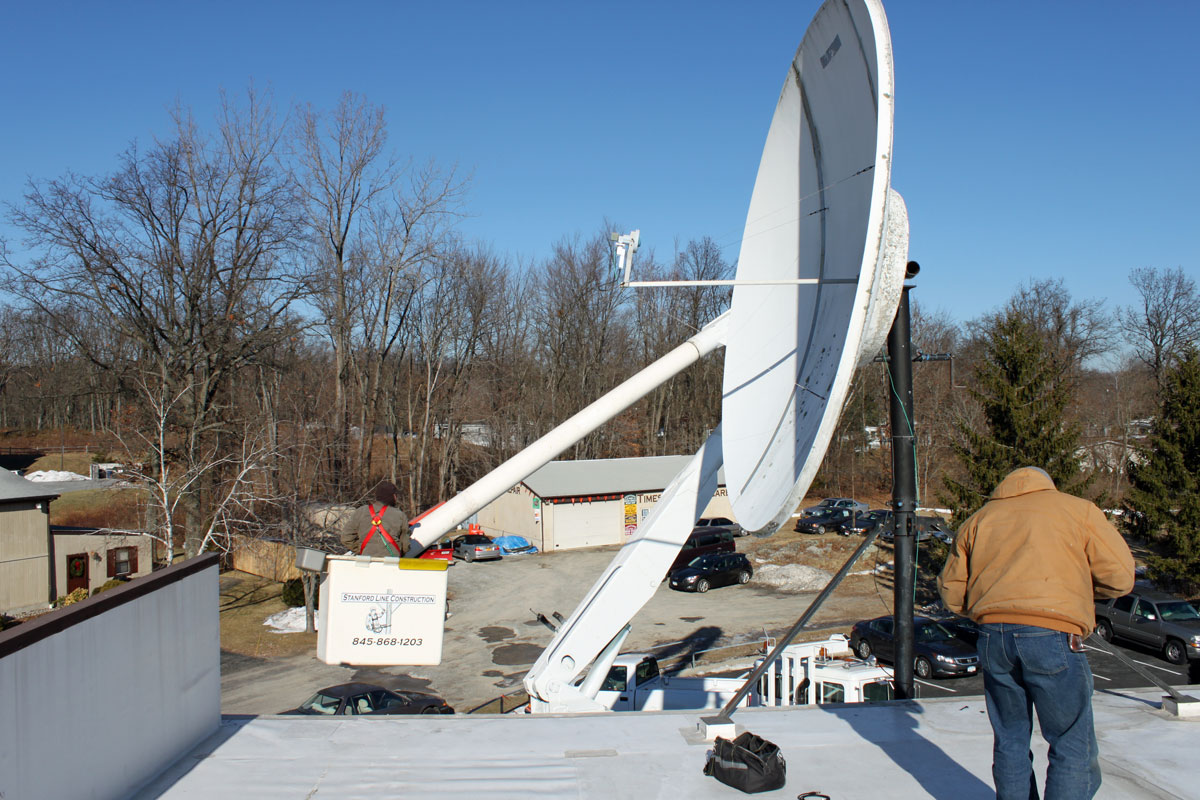
The real issue is doing nothing with the feed horn assembly, as it hangs way up in the air right over the edge of the roof. An extension ladder does not work, nor does a step ladder on the roof. Thus, we had to call a bucket truck to come and replace the LNB. Naturally, this work is being done on one of the coldest days of the year (so far). Temperatures at the start were 4° F or -15° C, which made the hydraulics in the bucket truck a bit reluctant to work.
When the dish was installed in 2000 or so, I swung it so the feed horn assembly was over the roof to work on it. This did not allow me to effectively check the feed horn polarization. With the bucket truck and a good satellite aiming device, I was able to find the correct polarization for the transponders in use by this station.
Bucket truck satellite dish maintenance
The old LNB was an original California Amplifiers PLL LNB from the mid 1990’s. The temperature was 35° K, which is kind of high these days. It was replaced by a Norsat C band PLL LNB with a 20° K temperature.
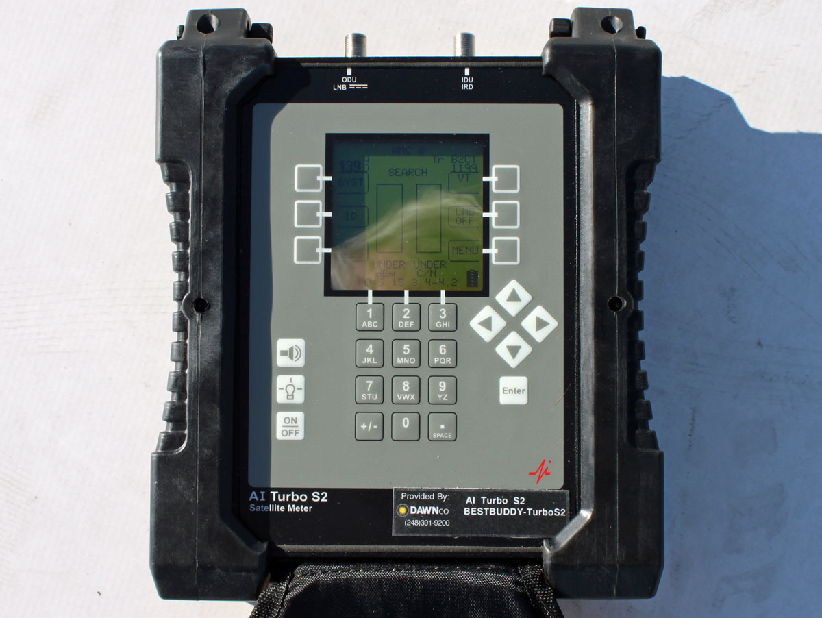
The satellite aiming tool used is an AI Turbo S2 by Dawn Satellite. This unit has software profiles for each satellite which can be updated over the internet. The 139° W satellite neighborhood is pretty crowded and it is easy to find yourself looking at the wrong bird. Using the aiming tool prevents that from happening, as it tells the user exactly which satellite it is receiving.
Satellite aiming tool
If this is a new installation, using Satellite Finder makes the rough aiming much easier.
Dish pointer, AMC-8 aiming information
Also, it one were interested in being very thorough, consulting the SES center of box page will give the best aiming window times. To be honest, I have never found this to make much difference.
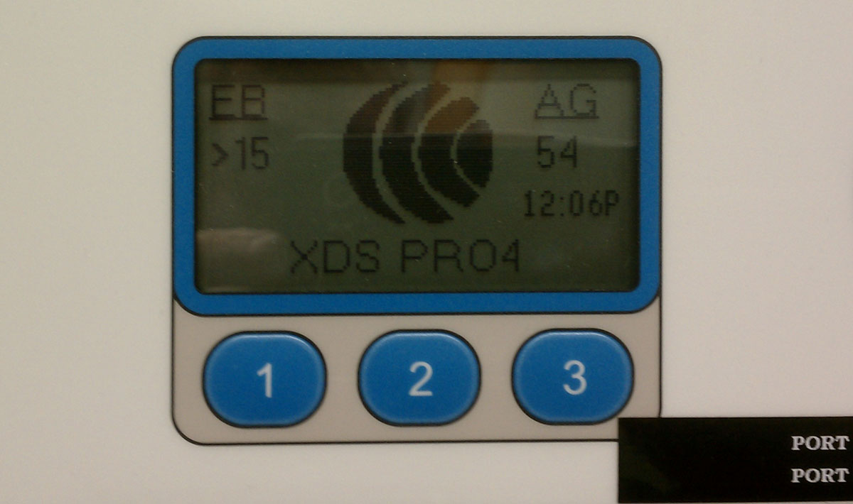
XDS Eb/No after re-aiming
The end result, Eb/No is 17.5 with an AG of 54. All in all, a happy satellite receiver.
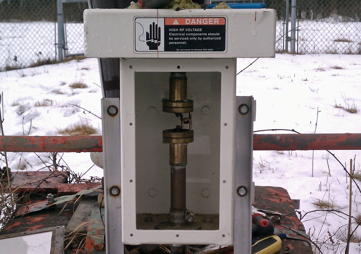
Had a problem with this Kintronic FMC-0.1 isocoupler the other morning.
Kintronic FMC-1.0 STL isocoupler
After an overnight drenching heavy rain and very high wind, the STL transmitter associated with this unit was having high VSWR faults. This isocoupler crosses a base insulator of an AM 50 KW directional antenna. This particular tower has negative impedance, which is to say, it sucks power out of the pattern and feeds it back to the phasor. An interesting discussion for another time, perhaps.
Using a dummy load, we isolated the problem to the isocoupler by first connecting the load to the output on top of the unit (the problem still exists) and then to the transmission line prior to the unit (the problem went away). Of course, the AM station had to be taken off the air to do this work.
Once the issue was confirmed as the isocoupler, I opened the unit up and found that water had entered and pooled in the top of the bottom half of the isolation transformer.
Kintronic isocoupler transformer
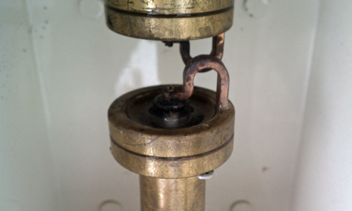
The isolation transformer consists of two loops to ground capacitively coupled through air dielectric. The issue is with the opening around the top of the unit, under the lip of metal lid. Apparently, this allowed water in.
Kintronic isocoupler isolation transformer
It is difficult to tell with the lighting in this photograph, however, the bottom part of this isolation transformer has water pooled around the center insulator. Using a rag, I cleaned out the water and dirt from the center insulator. After reconnecting the antenna and transmitter transmission line, a quick check revealed the problem was much better, but still not completely gone. I suspect water seeped further down into the bottom half of this unit. The repair work was good enough, however, to return both stations to the air.
Glad to get that bit of work done while it was still relatively warm out.
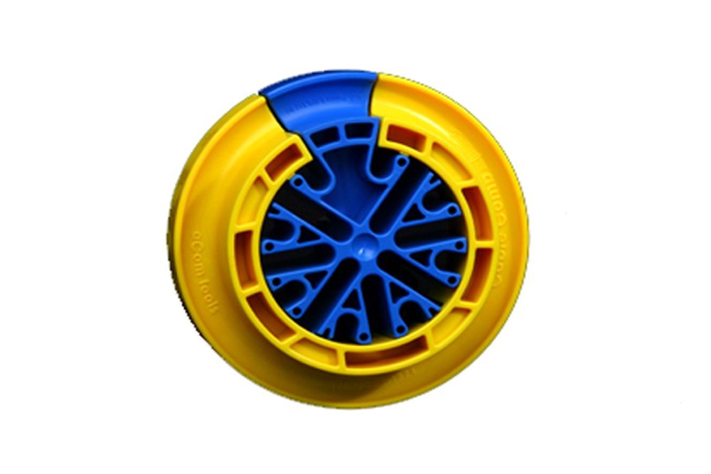
On occasion, the company I currently work for does installation work. Thus, I am always keeping my eyes open for new equipment and tools to make that job easier. The cable comb seems like it is just such a thing:
ACOM tools cable comb
Instructional video from youtube:
Then there is this:
Which is simply amazing. It is described as “1320 Category 6 cables, dressed and terminated.”
Incidentally, there is an entire subreddit: reddit.com/r/cableporn for all those cable geeks that like to look at neat cabling work.