I found this video on YouTube about WEQX, Manchester, Vermont. WEQX is a class B FM station with its tower located on Mount Equinox. This gives the station a huge signal with a HAAT of 759 meters and 1,250 watts of power. It comes in well south of Albany and while I am in the Albany area, I enjoy listening to it.
This piece is by CGTN, and one wonders how they ended up in Manchester, VT of all places.
The information below the video is also an interesting read. In part it goes into corporate ownership of radio in the US, stating:
In 1983, 90 percent of U.S. media was controlled by 50 corporations. Today, just six corporations control that 90 percent… Among the 10% (of radio stations) currently not controlled by those six corporations is an alternative rock station in the Green Mountains of Vermont.
That is misleading. The “six corporations” they are referring to date back to an article published several years ago. They are; Time Warner, Walt Disney, Viacom, News Corp, CBS, and NBC/Universal. As of this writing, none of those companies listed owns any radio stations. Further, the media scene in general has become much more fragmented with the advent and greater acceptance of things like Pod Casting, YouTube, and other social media.
There are three big radio station owners, which together own 1,613 radio stations. That represents approximately 14% of the licensed commercial AM and FM stations in the US. There are several medium-sized owners; Entercom (237), Salem (118), Saga (108), Midwest (75), Forever (69), Beasley (63), and so on. While iHeart (851), Cumulus (442), and Townsquare (320) influence the way other station owners operate, by and large, the majority of radio stations in this country are still owned by small business owners. Stations that are keeping it local continue to be noticed and hopefully rewarded with a successful business.
WEQX is certainly a unique station and it always has been. In the late ’90s and early ’00s, I did some work for them at various times. It was always fun and I enjoyed it.
As a former Coast Guard Radio operator who spent many minutes synchronizing clocks, I find this pretty funny:
The funding for WWV may be cut out of this years budget or next. Take a few minutes on 5, 10 or 15 MHz to reminisce. Then turn that thing off, it gets annoying after a while.
I am currently finishing an interesting project involving putting up two translators on a diplexed AM tower which also holds a mobile phone/data tenant as well. All-in-all, this seems to be a very efficient use of vertical real estate.
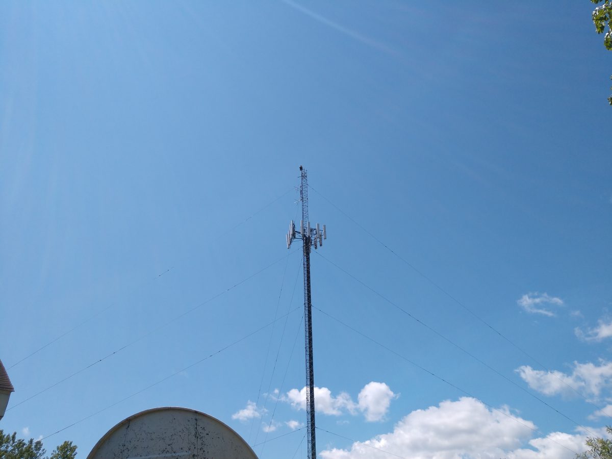
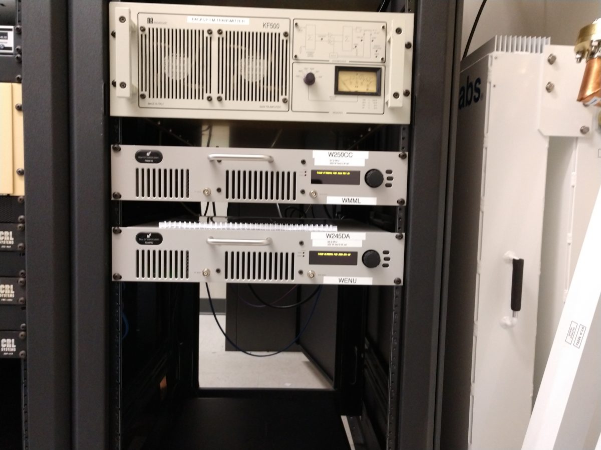
WMML WENU tower, Glens Falls, NY
The AM stations are WMML and WENU in Glens Falls, NY. The AM stations are diplexed using a Phasetek diplexor/ATU.
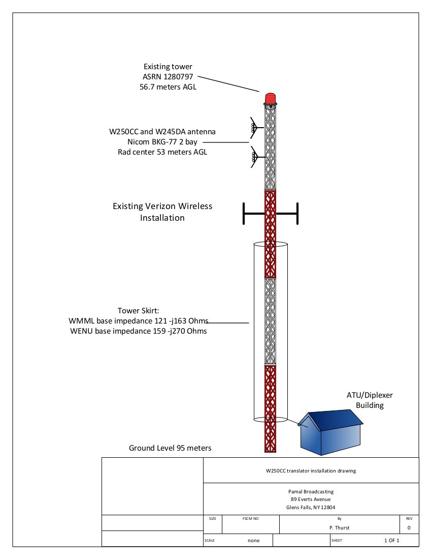
Diagram showing WENU/WMML tower with W250CC/W245DA antenna installedDiplexor diagram, WENU/WMML Glens Falls, NY
The translators are W250CC and W245DA which are using a NICOM BKG-77/2 two bay 3/4 wave spaced antenna mounted at 53 meters AGL. The translators use a Shively 2640-04/2 filter/diplexor which is a broadband input port in addition to the translator input ports. Since these translator signals are only 1 MHz apart, the higher-power Shively filter was installed because it has better rejection characteristics. The broadband input port allows the NICOM antenna to be used as a backup for any of the three FM stations; WKBE 107.1, WNYQ 101.7, or WFFG 100.3. Two transmitter sites for those stations are mountaintop locations which are very difficult to get to in the wintertime. Having a backup site available takes some of the pressure off during storms or other emergencies.
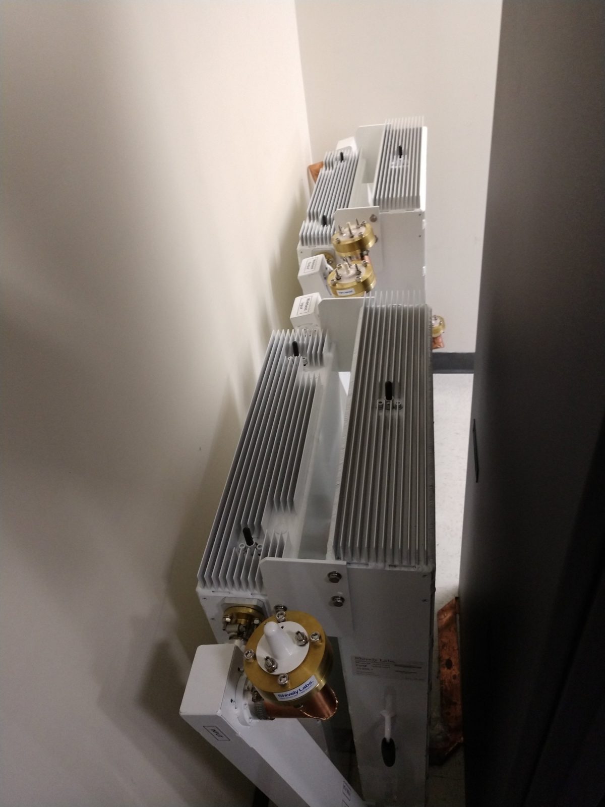
Shively 2640 -04/2 filter for W250CC and W245DA
The NICOM FM antenna was mounted on the tower when W250CC went on the air in October 2016. When it was installed, the base impedances for both AM stations were measured. For some reason, WENU 1410 KHz seems to be more sensitive to any changes on the tower, thus the WENU ATU needed a slight touch-up. When working on diplexed AM systems, it is also important to make sure that both trap filters, which are parallel resonant LC circuits, are tuned for maximum rejection of the other signal. During this particular installation, nothing was added to the tower and no change in the base impedance for either station was noted.
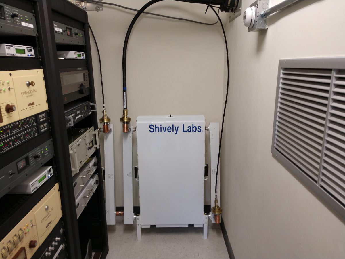
Shively Filter, connected to transmitters and antenna
As a condition of the construction permit, measurement of spurious emissions of all stations sharing the common antenna needed to be completed to ensure compliance with FCC 73.317(b) and 73.317(d). I made careful measurements of the potential intermod products between the two translator frequencies. This measurement was completed with my TTI PSA6005 spectrum analyzer.
The primary concern here is mixing products between the two transmitters. Both transmitters are BW TXT-600 with low pass filters before the output connector. There are three frequencies of interest;
(F1 – F2) + F1 or (97.9 MHz – 96.9 MHz ) + 97.9 MHz = 98.9 MHz
That, plus harmonic measurements out to seven or eight harmonics of the fundamental frequency should be enough to demonstrate compliance with FCC out-of-band emissions standards. Being that this site has LTE carriers, it is very important to measure the harmonics in those bands. Mobile data systems often use receiver pre-amps, which can amplify harmonics from the FM band and make them look out of compliance. Having a base set of readings to fall back on is always the best course in case the “out of tolerance” condition gets reported to the FCC.
Measurements on these frequencies must meet the emissions standards outlined in FCC 73.317 (d), which states:
Any emission appearing on a frequency removed from the carrier by more than 600 kHz must be attenuated at least 43 + 10 Log10 (Power, in watts) dB below the level of the unmodulated carrier, or 80 dB, whichever is the lesser attenuation.
Harmonic frequencies to be measured:
Harmonics for 96.9 MHz fundamental
Harmonics for 97.9 MHz fundamental
Comments
193.8
195.8
290.7
293.7
387.6
391.6
484.5
489.5
581.4
587.4
678.3*
685.3*
US LTE Band 71
775.2*
783.2*
US LTE Band 5
872.1*
881.1*
US LTE Band 5
969.0
979.0
*Frequencies that fall within the mobile data LTE bands. Traces were recorded and saved for these frequencies.
All of that information, once compiled is attached to the FCC form 350-FM, which, once filed grants Program Test Authority.
BW TXT-600 V2 translator transmitters under test and measurement
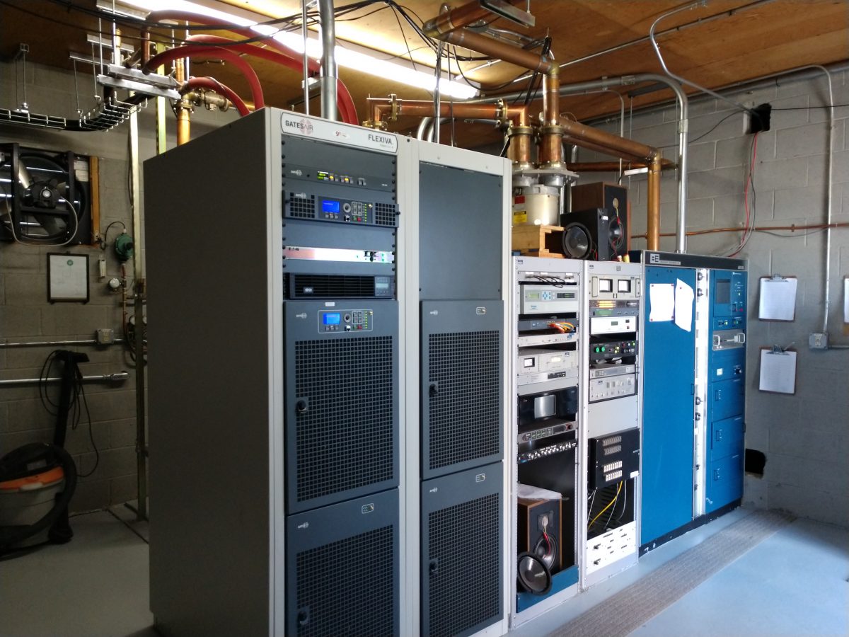
I was at the WEBE transmitter site recently and took the time to look over the transmitter we installed last year:
GatesAir FLX-40 transmitter, WEBE Bridgeport, CT
Overall, I would say that this transmitter has been very reliable. We had to install a UPS for the exciter and HD Radio exporter, but that is not a big deal. During the first power outage, the exciter went dark first. It took longer for the transmitter controller board to lose power, in the interim the controller turned the transmitter power all the way up. When the generator came online 10 seconds later, the transmitter returned to operation at 41.5 KW. This, in turn, caused one of the other field engineers to freak out and nearly lose his mind (stay away from the brown acid, FYI).
I installed the UPS a few days later.
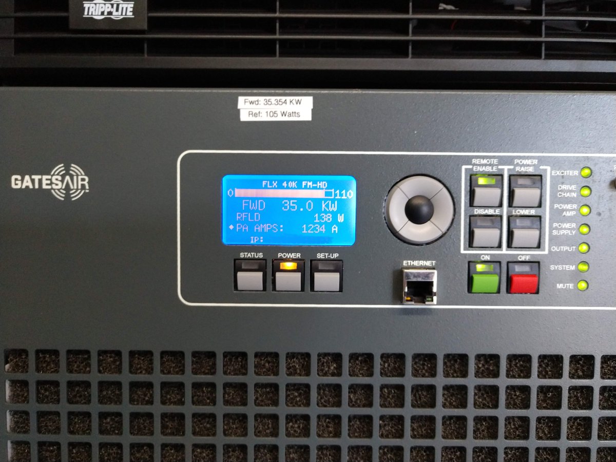
WEBE TPO 35.3 KW with HD Radio carriers on
The transmitter power output is 35.3 KW, which is getting into the semi-serious range. The reflected power goes up when it gets warm out and goes down in colder weather. Over the winter, it was running about 50 watts. Even at 138 watts, that represents 0.004% reflected power. The TPO forward goes to the 6 bay, 1/2 wave spaced antenna side mounted, 470 feet (143 meters) AGL. The station covers pretty well.
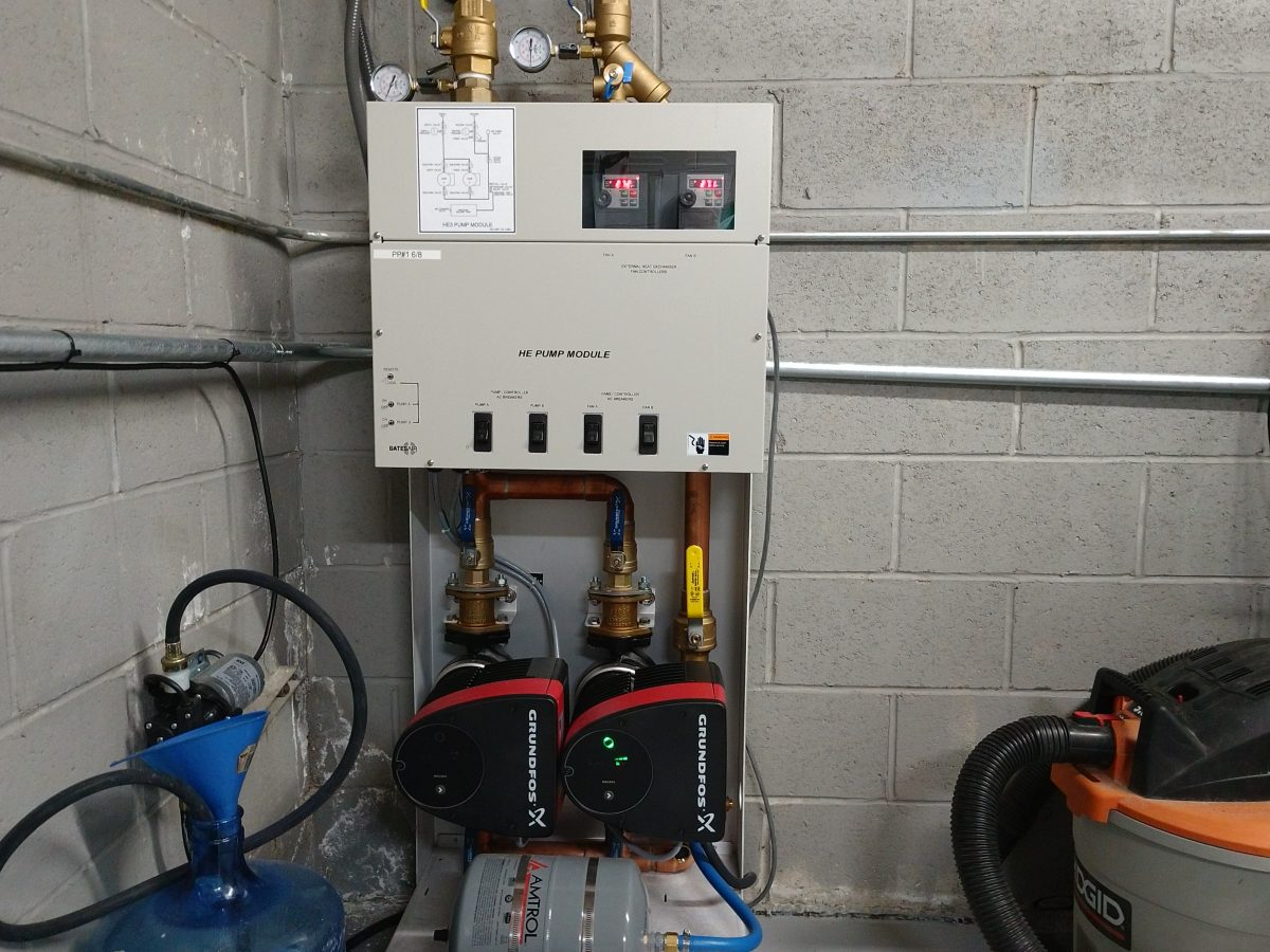
WEBE Pump station, pump is running 2/3 speed and fans are running at about 1/2 speed
Overall, I would give the liquid cooling system an A grade. The transmitter still dumps a fair amount of heat into the room from the RF combiners and PA power supplies. Most of the heat, however, ends up outdoors. Previously, we had two Bard 5-ton AC units running almost full-time. Now, only one AC unit cycles on and off except for the hottest days of the year. The outside temperature when this picture was taken was 81 degrees F (27.2 C).
Next year, we will have to send a sample of the coolant to be analyzed.
Gates FLX-40, WEBE Bridgeport, CT
I have had good experiences with the GatesAir FLX/FAX series transmitters. I would recommend this to a friend.