This is an interesting project currently underway at one of our client’s AM sites. They have decided to go all in and create a WISP (Wireless Internet Service Provider) for the community around the AM tower. I thought it would be interesting to explore this topic, as there are not many opportunities for AM towers to lease vertical real estate.
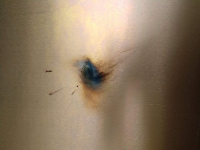
First a few basic ideas. For an AM broadcaster, (aka medium wave or standard broadcast band) the entire tower is part of the transmitting antenna. There are two types of towers; series-excited and shunt-excited. A series excited tower has a base insulator, like this:
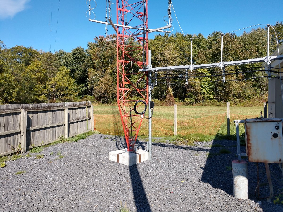
A shunt tower usually has a series of wires called a skirt, separated from the tower by standoffs, which go to the top of the tower or nearly to the top of the tower. The base of the tower is grounded, like this:
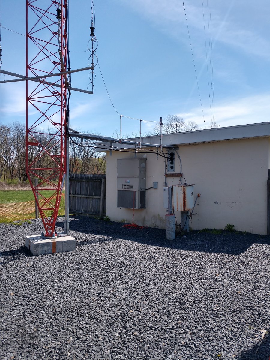
A shunt-excited tower has distinctive advantages for co-location opportunities in that the tower itself is grounded, greatly simplifying placing additional antennas on the towers. That is not to say that antennas can not be installed on series excited (insulated) towers, it just requires an extra step of using isolation coils.
In all cases, the tower should have a structural study done to insure that the additional antennas do not overload the tower and cause structural damage or collapse.
In this case, the tower is new and was designed for the extra load.
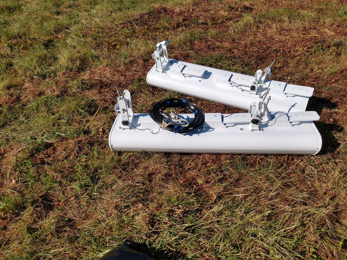
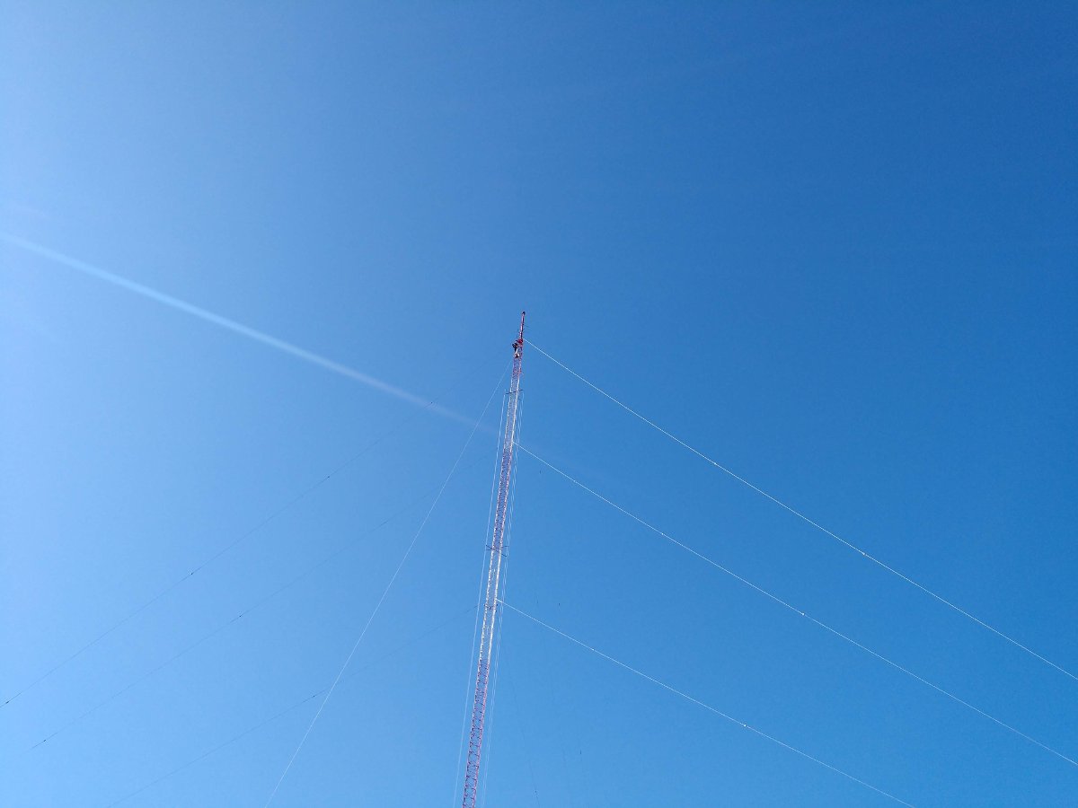
The plan is to create a sectorized wireless internet system using four 90-degree panels, each with three access points. A tower-mounted sixteen-port switch is mounted behind the panel antennas and the switch communicates with the ground-mounted router through two fiber optic cables. A 54-volt DC supply powers the switch, access points, and point-to-point radios mounted on the tower. There are two fiber runs, one is for subscriber traffic and the other is for radio management. This system is using Ubiquiti gear.
A word or two about Ubiquiti gear. Ubiquiti specializes in cheap equipment manufactured in China. That is a double-edged sword. On the plus side, if anything breaks or gets damaged by lightning or whatever; throw it out and install a new one. On the negative side, I have seen Ubiquiti gear do some strange things, particularly after a firmware upgrade. The newer stuff seems to be better than the older stuff. All that being said, as this is a brand-new operation and seems to be a proof of concept, then the Ubiquiti gear will be fine to start with.
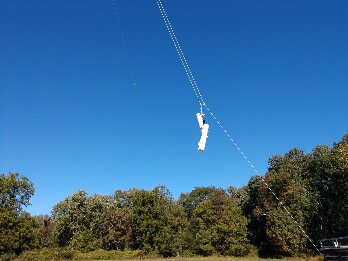
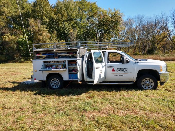
The tower crew made quick work of installing the sectorized access points.
Going up the face of the tower, there are the aforementioned fiber cables, the 54 VDC power cable, and one backup Ethernet cable. All of the Ethernet jumper cables used to connect the access points to the switch are UV-rated, shielded Cat 5e, and use shielded connectors. This is very important on a hot AM tower. Due to the skin effect, the shield on the shielded cable protects the interior twisted pair conductors from the high AM RF fields present on the tower.
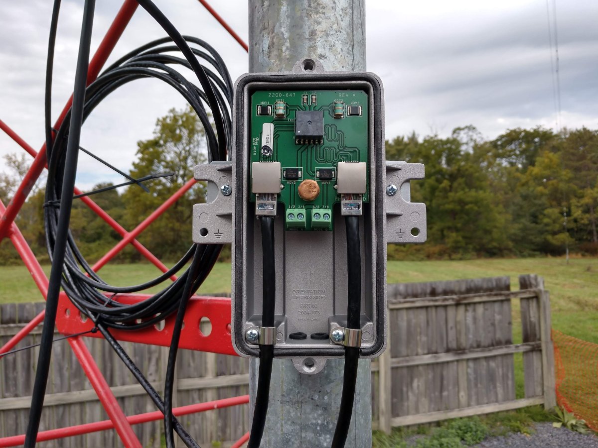
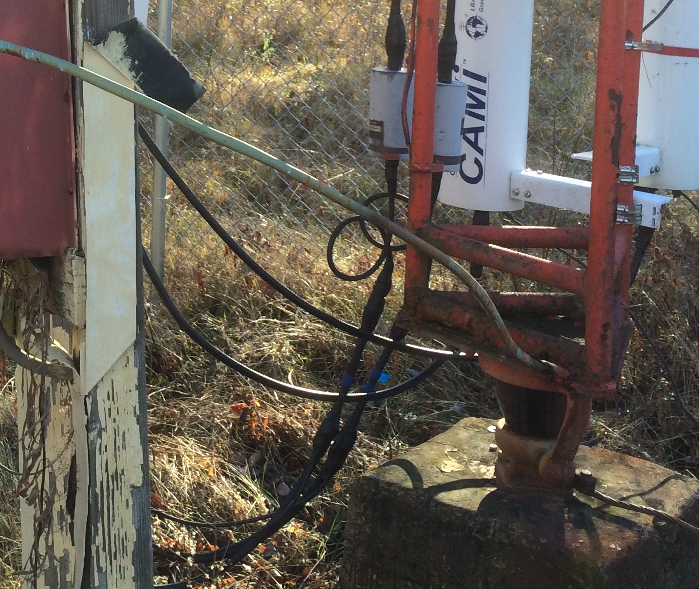
At the base of the tower, the DC power cable and the Ethernet cable go through high-quality lightning protection units. These are Transtector 1101-1158 Ethernet and 1101-1025 48-volt outdoor DC power units. Even though the DC power supply is 54 volts, the 48-volt LPUs will function adequately. The TVSS devices used in the LPU circuit are rated for 88 volts maximum continuous voltage.
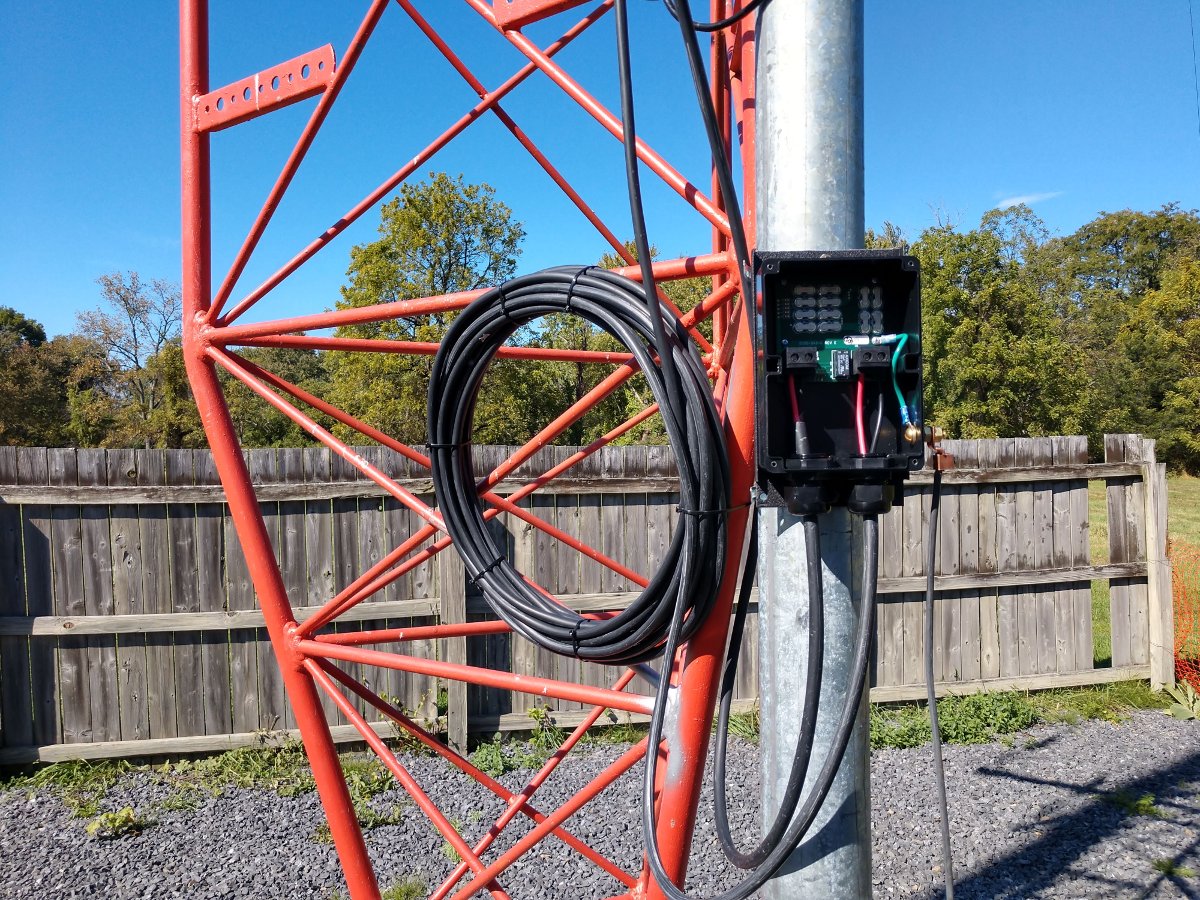
In addition, I made a service loop on the DC cable with also creates an RF choke. Several (12-14) turns of cable 18-20 inches (45 to 50 cm) in diameter act to keep the induced RF at the input terminals of the LPU low so the protection devices do not fire on high modulation peaks. This also helps to keep the AM RF out of the 54 VDC power supply in the rack.
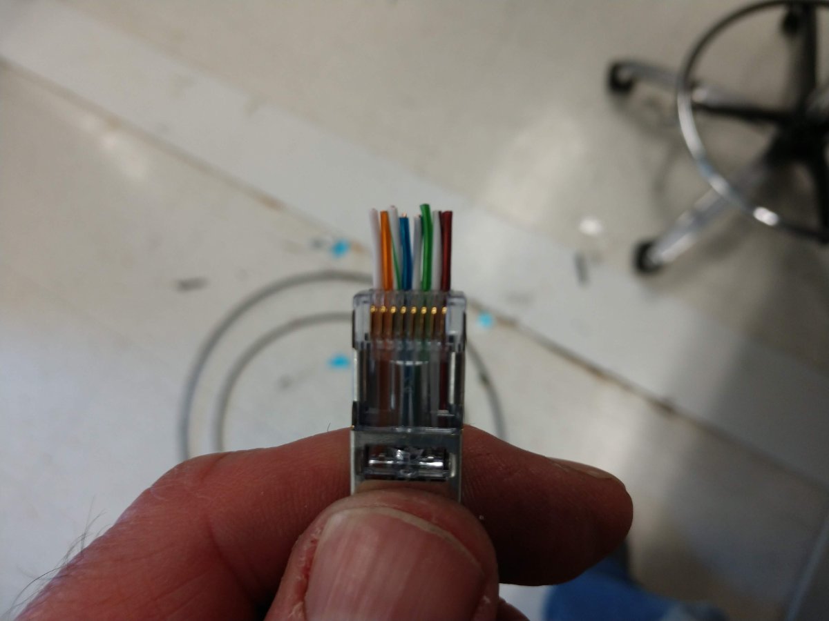
The backup Ethernet cable has a similar setup. Regarding the Ethernet cable and induced RF, this station runs 1 KW. As long as the shielded RJ-45 connectors are applied properly and the tower-mounted switch is grounded along with the LPU, then all of the RF should be on the very outside of the cable shield (due to the skin effect).
This principle also applies to lightning strikes. Although lightning is DC voltage, it has a very fast rise time, which makes it behave like AC on the initial impulse of the strike. The voltage induced on the shield of the cable will not affect the twisted pairs found deeper within the Ethernet cable. Of course, all bets are off if there is a direct strike on a piece of equipment.
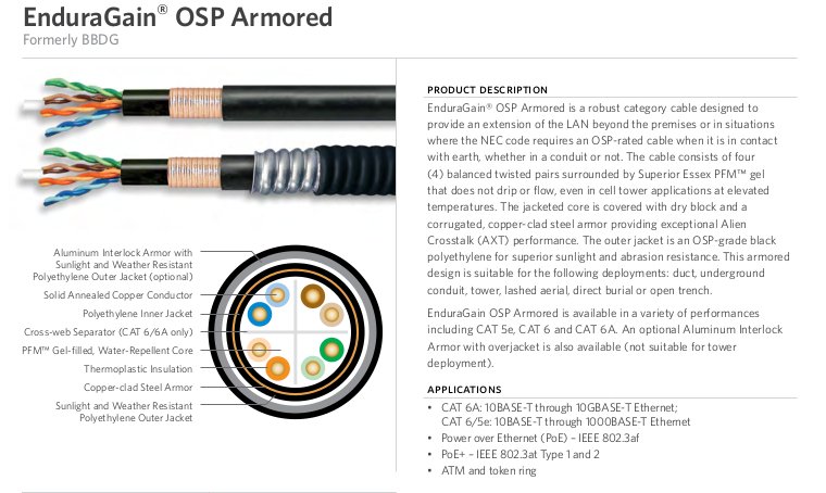
AM stations running powers more than 1 KW, Superior Essex makes armored shielded cable called BBDG (the new trade name is EnduraGain OSP). This cable comes with a heliax like a copper shield with an optional aluminum spiral armor. This cable looks very robust.
On series excited towers (those with an insulated base) fiber optic cable can be used to cross the base insulator without any problems, as long as there is not any metal in the cable (armor or aerial messenger).
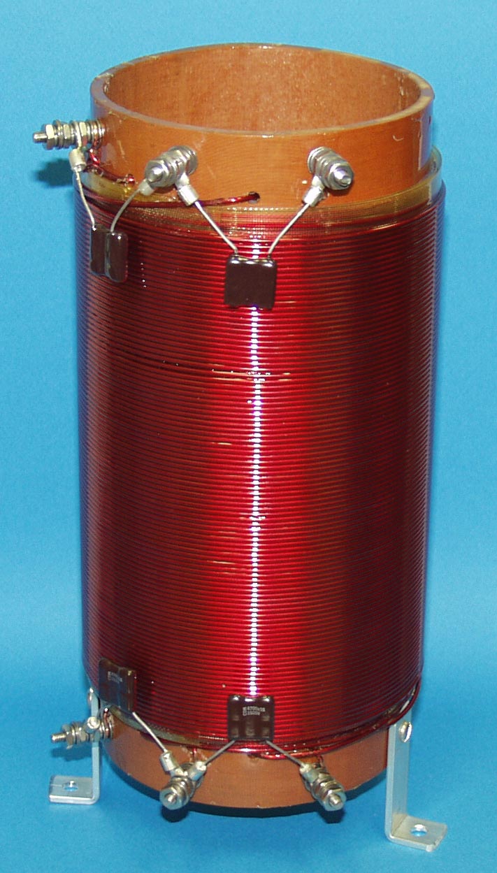
DC power can cross the base insulator using something called a “Tower Lighting Choke.” This device is a set of coils wound around a form that passes the DC power but keeps the AM RF from following the DC power cable to the ground. These work relatively well, however, lightning protection units still need to be installed before the DC power supply.