On this, the 98th anniversary of the sinking of the Titanic, some radio history is in order. Before broadcast stations, radio was mainly used by ships at sea sending messages in Morse Code to coastal radio stations. These messages could be routine; we are on schedule, we are carrying such and such cargo, request port clearance, etc. They could also be urgent; the ship is sinking, we need medical advice, etc.
Most of these early radio stations were owned by Marconi Company, which later became RCA. One of the first Marconi Stations was in Wellfleet Cape Cod, the original call sign was MCC (for Marconi Cape Cod) later changed to WCC.
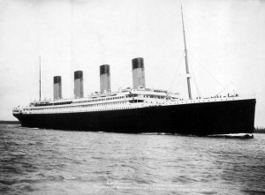
On April 14th about 11:45 pm, the Titanic struck an ice burg and sank about two and a half hours later. The RMS Titanic call sign MGY was equipped with a radio transmitter at a time when ships were not required to be. Sadly, the finer details of distress procedures for radio-equipped ships had not been worked out. After this incident, radio distress procedures were codified and the SOS evolved into an internationally recognized distress signal.
On the night the ship sank, the Marconi employed radio operators were sending routine traffic to Cape Race, Newfoundland radio. Because the radio apparatus used spark gap transmitters and crystal radio receivers, interference from other ship stations often caused problems. Earlier in the evening, a Titanic radio operator had strongly rebuked the operator from the closest ship, the SS Californian, telling him to “Shut up, shut up, I am busy; I am working Cape Race.” At about 11 pm the SS Californian operator retired for the evening and the Californian never received the distress call. Sadly, this incident probably led to the high loss of life because the Californian was just over the horizon to the west and would have likely been able to rescue many of the passengers before the Titanic sank.
Coast Guard radioman Jeffrey Herman has a good SOS story from the late 70s. Being stationed in Hawaii, he was on duty late one night at Coast Guard Radio Station Honolulu, call sign NMO.
John Davies, the radio operator on board the Eriskay also has a story about receiving an SOS while at sea. Fortunately, that one turns out a little better.
I remember one night, hearing an automated SOS on the international lifeboat frequency (8364 kHz). I imagined some poor guy cranking the lifeboat radio not knowing if it was going out or not (I was right, it turns out). We heard him on Guam and DF’d him to off the coast near Australia. We notified the Australian authorities, who diverted a nearby ship that picked 26 survivors up the next morning.
I am sure there a quite a few old CW (morse code) radio operators out there that have similar stories. By the 1990s most maritime communications had moved to INMARSAT, and CW and coastal radio stations became redundant.
The end of commercial Morse Code in the US came on July 13, 1999, when KFS, the last coastal radio station, signed off. Most of them have been scrapped and the valuable coastal land sold off to developers.
The development of broadcast radio was a direct offshoot of these radio stations. AM radio, or rather AM technology was developed by ATT as an adjunct for their long-distance system. ATT used High Frequency (HF) voice circuits to span oceans for several decades, up to about the mid-1960s. Amateur radio operators began fooling around with voice broadcasting, using ATT’s patented AM technology around 1915 or so, after tube-type transmitters and receivers became available. Somebody realized that money could be made with the new-fangled radio contraption and commercial broadcasting was born.