I learned this one the hard way, all climates, and terrain are not equal. An important detail when planning a Studio to Transmitter Link. The RF STL is usually in the 950 MHz band, although lately, people have been using 2.4 and 5.8 GHz unlicensed systems with good results. What works well in the northeast, for example, might not work that great in Florida, where tropospheric ducting and multi-path can create reception problems.
One example of this happened in Gainesville, Florida. A station there had a 15-mile path over flat ground with tall towers on either end. It had full line of sight and Fresnel zone clearance. Ordinarily, the signal strength was -65 dB, which is about 25-30 dB of headroom for the equipment being used. However, in the mornings, most often in the late summer or early autumn, there would be brief dropouts of a few seconds. After two years of suffering through the mysterious morning dropouts, we finally rented a plane and flew the STL path, only to discover there was a swamp right in the middle that was not on the topographical map. On those mornings when dropouts occurred, it was surmised that dense fog would rise up, causing the RF path to bend and creating multipath at the receive antenna. Since it was a Moseley Starlink, the digital demodulator would unlock due to high BER. The signal strength never moved off of -65 dB.
Of course, had this been an analog STL, it would not have dropped out, although it may have gotten a little noisy for a few minutes.
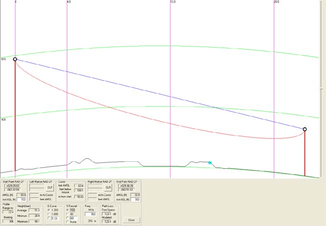
I have learned to be very conservative with my STL path analysis, using software tools like RF Profiler to look at the theoretical path, but also surveying ground obstacles like trees and buildings, which are not accounted for in the USGS terrain database. There are several RF software programs out there that will do the same thing.
Last week, when a station manager insisted that an STL path was possible from a proposed new studio location, I deferred to the path study, which showed only about 50% Fresnel zone clearance. While it was true that the path is less than a mile, and it is also true that one can see the top of the transmitting tower from the roof; trees, buildings, and even an access road create problems that could potentially cause STL dropouts. We are not going down that road again. The station manager, whose background is in sales, was told to find another location or order a TELCO T-1.