It was a hot day, it was a cold day. The tube transmitter was running, the solid-state (HD-1) transmitter was off the air. The books show that the company has deep pockets, but the accountant has short arms. And so it goes. In a sordid, yet familiar tale of leaping three-quarters of the way across a river, the builders of this transmitter site seemed to think of everything except the cooling requirements for a 35 KW FM transmitter.
Instead of installing real commercial AC units, someone decided that 34,000 BTU window units were the way to go. At one time, there were eight of those units, all single phase 240 volts sucking down gobs of power and freezing up when the outside temperature dropped below 40°F. This was always a problem but became more so when we took over the maintenance of this site. When there was a full-time engineer, his time, apparently, could be wasted running back and forth turning the window units on or off in the winter as required. Now that a contract company is doing the work, it becomes cost prohibitive to require such things.
Therefore, the time had come to make a change. To that end, six of the 34,000 BTU window units were removed from the building. Two of the existing holes in the wall were used to create an emergency cooling system, consisting of a 4,292 CFM fan and a couple of shutters. Two other holes were used for the new air conditioners and two holes were blocked up. The remaining two window units were left in place in the combiner room, which is a separate cooling zone.
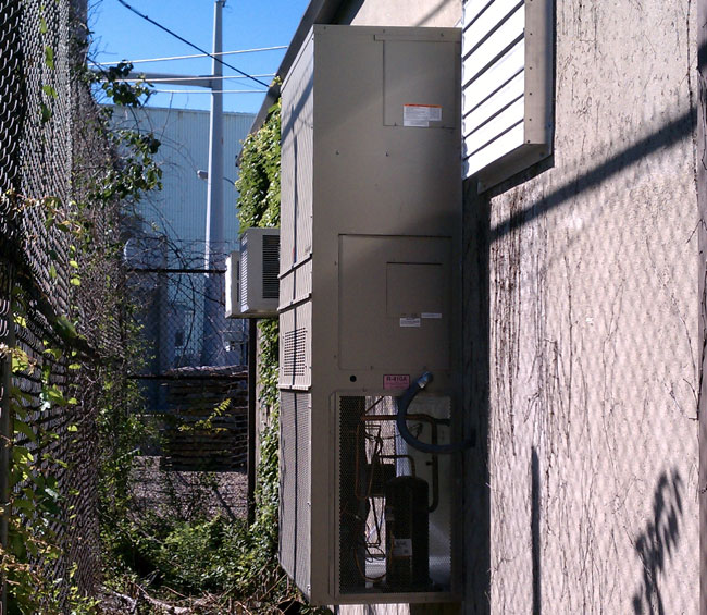
The new ACs are five-ton wall-mount Bard units. These are three phase and should be more than enough to keep the transmitters cool. Here is how I arrived at that conclusion:
- The entire building load when the main transmitter is running at full power, without the transmitter room air conditioning, is 60 KW.
- All of the building loads except the transmitters go through a single-phase panel.
- The load on the single phase panel is 10 KW, thus the transmitter load is 50 KW (this 10 KW is mostly the single phase AC units in the combiner room)
- The TPO is 32 KW, therefore the transmitter is generating 18 KW of waste heat.
- One watt-hour = 3.412 BTU of energy, thus
- 18,000-watt-hours equals 61,416 BTUs
- One ton = 12,000 BTU, thus
- 61,416 BTU ÷ 12,000 BTU = 5.118 tons
That will take care of the main transmitter waste heat. The HD transmitter generates another 4,000 watts of waste heat or 1.37 tons. The combiner is in another room and doesn’t factor into the calculation. The rest of the equipment is inconsequential, adding up to less than 100 watts.
The solar gain is more difficult to calculate, as it is based on the building structure, the type of construction, and the heat gain (loss) through the walls and doors. This building is concrete block, insulated, and has no windows. It is unshaded, however, it is painted a light color. All in all, the solar gain should be less than two tons on a hot day. Therefore the total AC load should be 8.25 tons or less.

All that is left now was to install the things. Just pull up the truck and use a crane to lift them in place, except, no; that plan won’t work. This is the transmitter site at the power plant and the 138 KV lines overhead precluded any lifting with a crane. We instead had to build ramps and move things around on large-hand trucks. One unit is installed on the rear of the building, the other on the front. It required several days to make the ramps and four people to muscle the things into place.
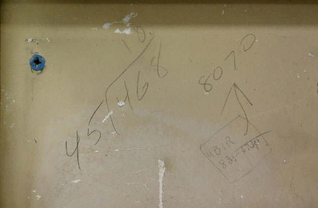
The bottom air intake holes needed to be cut out for the new units. Cutting into the concrete block while the BE FM 35A was running proved to be another challenge. We used several sheets of plastic, shop vacs, and extra air filters on the transmitters to keep the concrete dust out of the PA cavities and motor bearings.
Plan B cooling consists of a 4,292 CFM Venturi fan mounted on the rear wall of the building. The fan is controlled by a ceiling-mounted thermostat set to 95 degrees. If the AC’s fail, the ceiling temperature will rise and the fan will turn on.
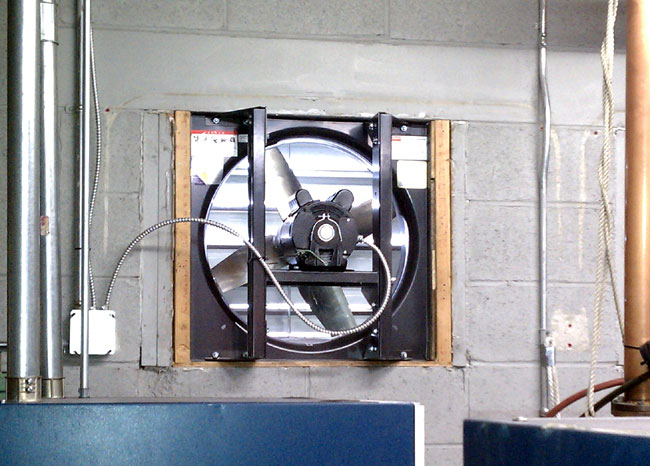
The room volume is about 3600 cubic feet, therefore this fan will change the room air about once every 60 seconds or so. It is not the best plan to move humid, potentially dirty outside air through a building, but it it keeps the station on the air while the main AC units are being repaired, then so be it.
The entire system went on line last week and is working well.