What is this?

Or rather, what is the significance of this:

Wall Graffiti at a transmitter site
Wall graffiti at a transmitter site

A few hints; it was found (written on a wall) at an old, mountain top transmitter site. We are renovating this site and it was underneath an old old alarm panel from the 1970’s that I removed. It reads 468 ÷ 45 = 10.   and the 468 is significant.

Once upon a time, a person could go to the TELCO demark and get all of the inside numbers for the CO and any number of COs in the area.  They would be scribbled on the wall next to the equipment along with many other numbers.   This was especially helpful when doing emergency troubleshooting on a circuit that was down.  Try to do that these days and the most likely result is an unanswered phone.  Most of the smaller COs are not normally manned unless there is a trouble ticket in the process.

Tube transmitters vs Solid State transmitters

I thought it would be interesting to do a comparison between the two types of transmitters, both AM and FM.  I have been doing this thing for 25 years and have quite a bit of experience working on all types of transmitters.  Some of the broadcast transmitters I have personally worked on over the years include:

  • Harris: FM-20H, FM-5G, HT-35, HT-10, HT-3.5, FM-25K, FM-5K, Z5-CD, MW-50A, MW-50B, MW-1A, MW-5A, BC-5H, SX-5, SX-1A, Gates 1
  • Broadcast Electronics: FM-5B, FM 3.5A, FM5A, FM30A, FM35A, FM30T, FM20T, FM10S, FM5C, FM1C, AM10A, AM6A, AM5E, AM1A
  • Continental Electronics: 816R-2, 814R-1
  • Collins Rockwell: 831F-1, 838E-1
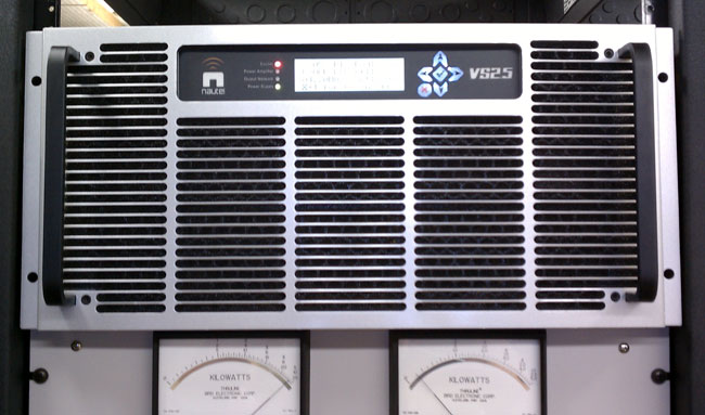
  • Nautel: ND-1, ND-5, XL-60, V-40, V-10, V-7.5, NV-40
  • Gates: BC5P, BC1T, FM5B
  • General Electric: BTA-25
  • RCA: FM20ES1, BTA5J, BTA1-AR
  • CSI/CCA, Visual, Energy Onix, Bauer, McMartin, QEI, some Italian something or other, etc.  Various makes and models.

I think I have a fair amount of transmitter experience under my belt.  What I have found is that certain brands of transmitters are better than others, regardless of whether they are tube or solid-state.  There are several differences in each type, obviously.  As to some blanket statement about which is better, solid state or tube, I don’t have one.  My statement would be “It depends.”

Tube transmitters are more rugged and will take more abuse than a solid-state unit. Things like heat, lightning, EMP, and mismatched antenna won’t phase a well-designed, well-manufactured tube transmitter.  On the other hand, they are less efficient AC to RF, have higher B+ voltages, have hard failure modes, and are more difficult to linearize, if that is required for some reason.

Solid state transmitters are more broad-banded, easier to change frequency, they have soft failure mode due to redundant amplifiers and power supplies. The voltages are lower, thus they are safer to work on.

Here is a complete list of advantages and disadvantages of each type:

AttributeTubeSolid StateComment
RuggednessVery rugged, able to take heat, EMP, lightning, mistuned antenna, poor operating environment, etcNot heat tolerant, lightning and EMP can damage MOSFETS, switching power supplies sensitive to AC mains issuesAdvantage: Tube
Electrical EfficiencyLess efficientMore efficientAdvantage: Solid State, however efficiency gain can be wiped out due to larger air conditioning requirement
Failure modeHard, most oftenSoft, most oftenAdvantage: Solid State, failure of a single module or power supply generally will not take unit off the air
Frequency agilityDifficultEasyAdvantage: FM Solid state transmitters can easily be moved.  AM transmitters still require extensive retuning.
Re-occurring costMoreLessAdvantage: Solid State, as tube changes are required every two to three years
MaintenanceSameSameAdvantage: neither
ServicingRequires skilled engineers to service and trouble shootModules and power supplies are often hot swappable and returned to manufacture for repairAdvantage: Solid State, however either type requires occasional measurements with specialized test equipment
Servicing safetyHigh voltages, contact will be fatalLower voltages, but can still be fatalAdvantage: Solid State
RedundancyLowHighAdvantage: Dependant on TPO, Higher powered solid-state transmitters are much more expensive than there tube type counterparts
CostLessMoreAdvantage: Dependant on TPO, Higher powered solid state transmitters are much more expensive than there tube type counterparts
AvailabilityGood used market, some new FM transmitters still being builtGood new and usedAdvantage: Tube
 Reliability Dependent on brand Dependent on brand Advantage: neither

For some reason, the latest Broadcast Electronics tube-type transmitters seem to have very long tube life.  I installed an FM20T at WYJB in Albany, New York,  in early 2001 and it is still on the original tube, some ten years later.  The same can be said for the 2005 FM20T and FM30T installation at WHHZ/WKZY, Gainesville, Florida.   Those tubes show no sign of giving up anytime soon.  I don’t know if that is an unusual trait of the transmitter or that particular tube.

WKZY, Gainesville, Florida

The above comparison seems to heavily favor a solid state transmitter.  As a general rule, brand new solid state transmitters both AM and FM have advantages in almost every category except high power FM transmitters, where tube types still make sense.  From a used transmitter standpoint, there is nothing wrong with a tube type transmitter, provided it has a solid state IPA.  I have noticed the 4CX250B driver tubes most often used in FM IPA stages have markedly reduced reliability of late.  I would also tend away from transmitter makes and models where the manufacture is no longer in business or no longer supports the product.

The Ground Loop

Audio Engineers will know this subject well.  Grounding has many purposes, including electrical safety, lightning protection, RF shielding, and audio noise mitigation.  Although all types of grounds are related in that they are designed to conduct stray electrons to a safe place to be dissipated, the designs of each type are somewhat different.  What might be an excellent audio ground may not be the best lightning ground and vice versa.  Sometimes good audio grounds can lead to stray RF pickup.

The basic ground loop looks something like this:

Ground Loop schematic

Where RG should equal zero, in this representation it is some other resistance.  This causes a different potential on the circuit (V1), which in turn causes current to flow (I1).  It is that unexpected flow of current that creates the problems, causing voltage (V2) to be induced on another part of the circuit.  In cabling applications, this will result in a loud, usually 60-cycle hum impressed on the audio or video being transmitted through the cable.

The resistance can come from something as mundane as the length of the conductor going to ground. This can often happen when using shielded audio wire in installations when the connected equipment is already grounded through the electrical plug.

There are two proven methods for eliminating ground loops, both of which are best implemented in the design phase of construction (aren’t most things).

Radio Station Common Point Grounding

The first is a single ground point topology, also known as a common point or star grounding system.  A common ground system consists of one grounding point or buss bonded together so that it has the same potential.  All grounded equipment is then connected to that point creating a single path to ground.  All modern electrical equipment has a path to ground via the third prong of its electrical cord.  Problems can or will occur when audio equipment is plugged into separate AC circuits, grounded via the electrical plug, and then tied together via an audio ground.  The longer the separate grounding paths, the more severe 60 cycle (or some harmonic thereof) hum can result.

To eliminate this problem, the shields should be broken at one end of the audio cable.  Never cut the third prong off of an electric cord, which can create another problem called electrocution.  Given the choice between a ground loop and electrocution, I’d stay away from electrocution, mine or somebody else’s.

For installations in high RF fields, the open shield or ground drain can act like an antenna.  In those situations, the open end can be bypassed to ground using a 0.01 uf ceramic disk capacitor. Electrically, this will look like an open at DC or 60 cycles, but allow stray RF a path to ground.   This problem can be a common occurrence when studios are co-located with transmitters.

Differential Signaling

The second is by using balanced audio or differential signals as much as possible.  This poses a problem for those stations that use consumer grade components, especially in high RF fields.  For shorter cable lengths, two or three feet, it is usually not a problem.  Anything beyond that, however, and trouble awaits.

It is relatively easy and inexpensive to convert audio from unbalanced to balanced.  As much as possible, equipment and sound cards that have balanced audio inputs and outputs should be used. In the end, it will simply sound better to use higher quality equipment.  Also, longer cable runs need to be properly terminated at both ends.

Installing equipment using good engineering principles and techniques will eliminate these problems before they start.

FM Stereo vs station coverage

There are a few FM stations around here that intentionally broadcast in mono.  One is an FM talker, which from a technical standpoint makes a certain amount of sense since any particular human voice is a single-point sound generator.

The other FM station broadcasting in mono, WKZE,  has a music format with a very eclectic playlist.  It is a full Class A located in northwestern Connecticut.  The idea with this station is to garner a larger and more reliable coverage area.

It comes down to a simple physics discussion about free space loss.  The basic equation for free space power loss is:

where:

That formula works for a single frequency, say the carrier frequency, for example. As the signal gets spread out by modulation, the power density on any given frequency is reduced as the energy is divided between many other frequencies.

First, free space loss takes into account the spreading out of electromagnetic energy in free space is determined by the inverse square law, i.e.

\ S = P_t \frac{1}{4 \pi d^2}

where:

  • \ S is the power per unit area or power spatial density (in watts per meter-squared) at distance \ d,
  • \ P_t is the total power transmitted (in watts).

Second, with Frequency Modulation (FM), the power spectral density is a function of the differences in the highest and lowest frequency:

 P=\int_{F_1}^{F_2}\,S(f)\,d f + \int_{-F_2}^{-F_1}\,S(f)\,df.

Therefore, the narrower the bandwidth of a signal, the higher the density of the received signal will be in relation to the transmitted power.  An unmodulated FM signal will have a better, more reliable coverage area than a modulated one.  Of course, we need to modulate the signal, otherwise, there is no point in having the transmitter on.

A baseband or composite FM signal has several components:

FM baseband signal
FM baseband signal

An FM station transmitting a mono signal will have a much lower bandwidth. With wideband FM, the modulation index is generally 2 or two times the maximum audio input frequency. Thus, a mono FM broadcast station will have an approximate deviation of approximately 30 kHz (plus any ancillary services like RDS) vs a stereo FM station, which has a 75-80 kHz deviation using the same carrier power.

For higher power FM stations, FCC Class C and B, this is not much of an issue.  Those stations tend to have a great deal headroom when it comes to power density, building penetration, multipath (picket fencing and capture effect).  For Class A and LPFM stations, it is a different situation.  For those stations,  unless FM stereo broadcasting is truly needed, it should be turned off.  On low power stations, stereo can be a great detriment to reliable coverage.