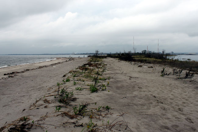
I figured if I have this problem, someone else probably has it too. We have a backup antenna on one of our towers. The station has a TPO of 28 KW, which is starting to get into the semi-serious level. This antenna is connected to Andrew 3-inch heliax that was installed in 1971. It has a spiral inner and outer conductor, which is no longer made by any manufacture of heliax.
We completely rebuilt the transmitter site a few years ago, moving a lot of things around. One part of the project was installing a coax port on the wall and moving all coaxial cables to that entrance. The main antenna is connected to Cablewave H50J coax. I ordered a new connector for that transmission line, no worries. When I cut the back up transmission line, I figured I could re-apply the old Andrew connector.
That is all fine, however, I removed the connector without reverse engineering it, that is to say, I didn’t pay close attention to how the inner and out conductors where cut, or how the jack was cut back. I will have to reverse-engineer the thing now.
Here are the steps I followed:
- Check out the CommScope – Andrew website for documentation. A search shows they only have the current connector, which is nothing like this one and will not work with spiral conductors
- Call Andrew and spend many minutes on hold or explaining to various helpers what I want. I was met with a universal “That is not an Andrew Part number,” or “Gee, I wish I could help but…”
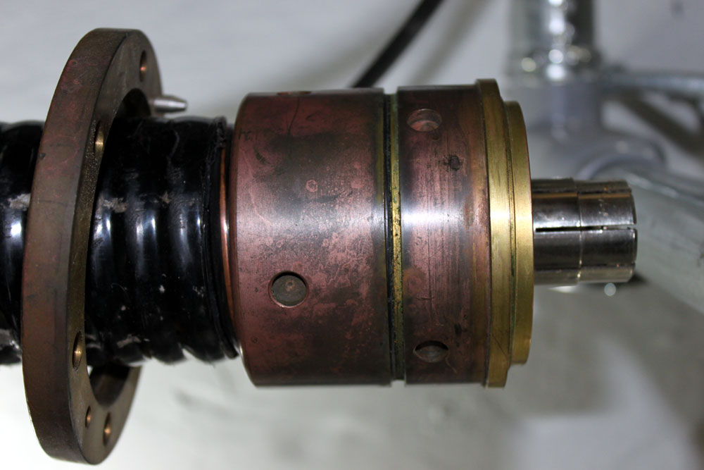
- Take the thing apart and begin measuring stuff with a ruler. Write everything down and draw out a diagram.
- Trim off the excess cable then practice putting the thing together once.
- Make the final cut and put the re-used connector back on the Andrew transmission line.
You can skip steps 1 and 2 since I already did them for you.
A few things to note:
- The inner and outer conductors should be cut flush and as close to perpendicular as possible.
- The inner conductor slug has a left-hand thread. This makes the slug tighten against the bushing.
- The outer jacket is cut back about 2.5 inches
- Place the EIA flange on the cable first, then thread the back nut onto the outer conductor, then thread the rubber gasket onto the outer conductor. The gasket is a tight fit, use petroleum jelly to lubricate it. This is a gas block connector, so special attention is needed with the gaskets.
- The inner conductor has triangular pieces 1/8 inch deep cut around the diameter, the depth of the inner slug is critical to the connector going together correctly.
- The inner conductor is folded inward over the end of the slug. Bushing, dielectric spacer, and EIA bullet are connected to the inner conductor slug and snugged down with a standard screwdriver
- The outer conductor is nipped 1/8 of an inch around the diameter
- The outer conductor is folded outward over the collect ring
- Use some petroleum jelly on all the O rings
- Carefully screw the connector together
- Final tightening requires a special spanner wrench or attachments for a socket wrench. The tower crew had these in their shop.
If you have a spectrum analyzer, check its return loss and see what it looks like before slamming a full load on it. If not, turn things on and bring them up slowly. Feel the connector to make sure it is not getting warm. If there are problems, heat will be the first warning sign.
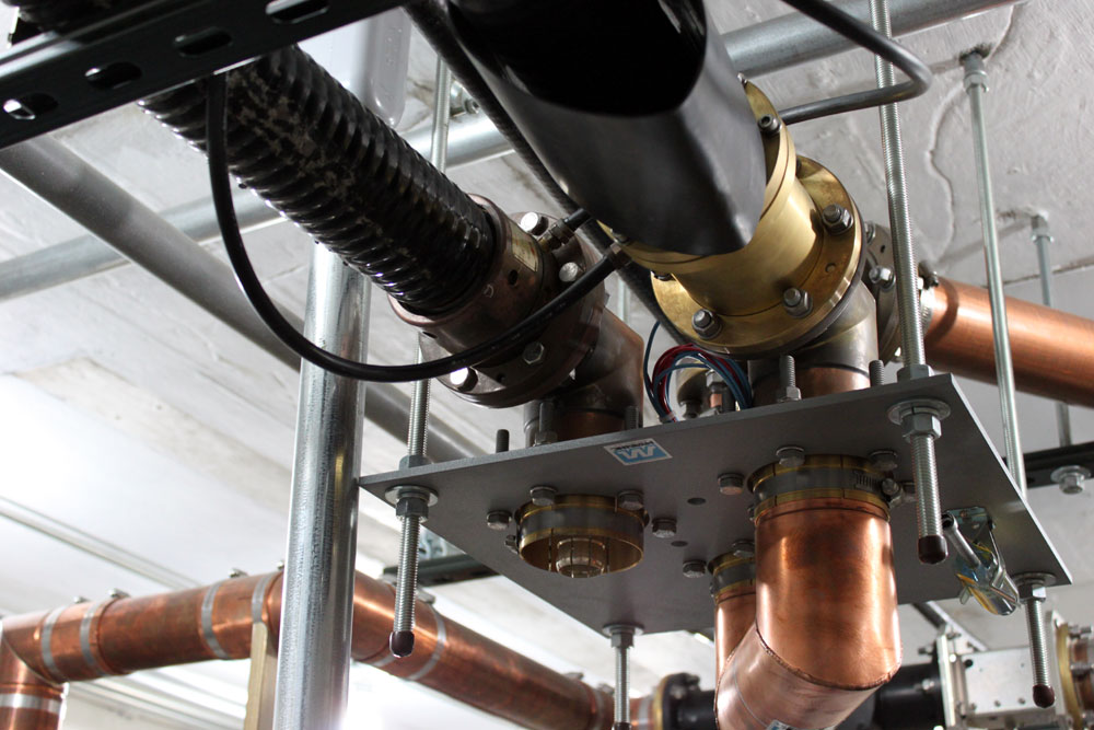
Once together, I ran the transmitters for a combined output of 10 KW and got about 50 watts return, which was much the same as it was before.