Many of the US’s earliest commercial radio stations are celebrating their 90th anniversary of broadcasting this year. I’ve seen announcements for WOR, WGY, and a few others.
It is fun to go back and look at the old pictures of those stations during the golden age of AM radio. If nothing else, it reminds us of what used to be and will likely never be seen again. Stations like WGY employed hundreds of people in their hay day; actors, musicians, announcers, news people, salespeople, support staff, engineers, etc. These days, WGY likely employs less than ten, certainly not more than twenty directly.
There are a few stations bucking that trend, but very few.
So here is to what once was and happy birthday to the hollowed-out shells of their former selves.
We are starting to work at a new client’s studios. It is a bit like stepping into a 1980s time machine, as the newest console seems to be the Broadcast Audio console in the FM studio. I feel I should wear a wide colorful tie and part my hair in the middle when working there. There is also an older UMC console in the second production room.
A what?
Exactly.
It seems the UMC console (UMC was a Connecticut-based console manufacturer that was later sold to Broadcast Audio) was having an intermittent hum problem on all the audio buses.
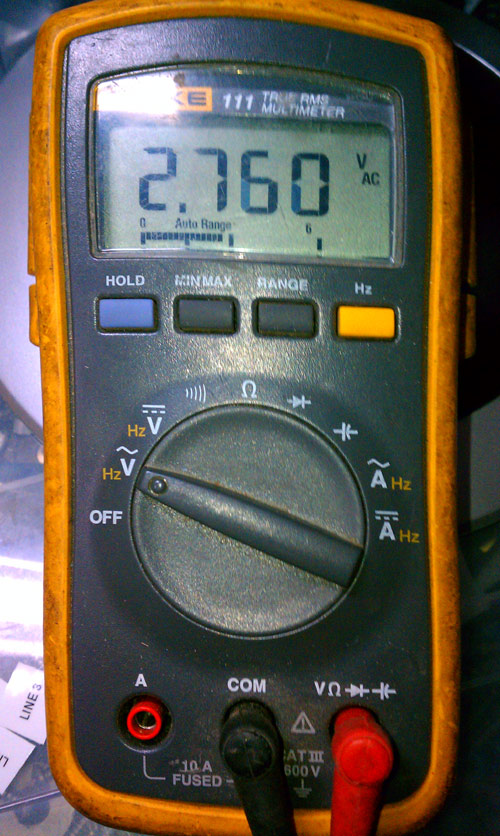
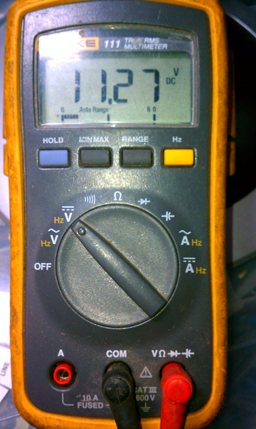
After poking around under the hood for a few minutes, I decided I should begin with the basics. Checking the power supply for ripple seemed like as good a place to start as any. This console has a 30-volt and a 12-volt power supply. The 30-volt supply checked out good, but the 12-volt supply, not so much:
12 volts DC, 2.7 volts AC12 Volt power supply
2.7 volts AC on the 12-volt DC power supply. That will put some hum on the audio, all right. I tried to replace the power supply main filter capacitor, but it had no effect. The regulator must also be bad and it is a Motorola part number which is likely not made anymore.
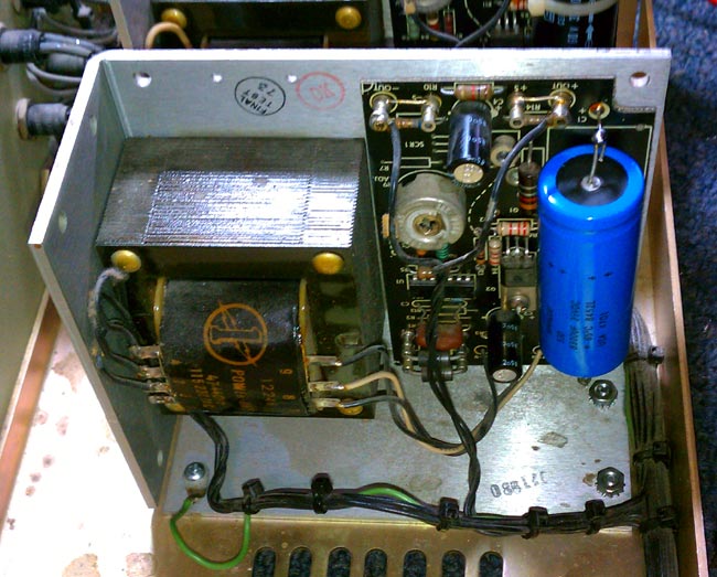
12 volt linear power supply
This is a pretty standard off the shelf power supply, I should be able to get one from Mouser for about $60.00 or so for a linear unit, which will be cheaper than us trying to trouble shoot and repair the old one. In the meantime, I took the 10 amp 0-30 volt bench supply and pressed it into temporary service. The console is working again, for now.
At some point, all this old, um, stuff needs to be replaced.
Several months ago, I drove up to an FM transmitter site, looked up at the utility pole, and saw this:
Three Phase open delta transformer bank
Three-phase open delta is a bad hombre. Most, if not all, transmitter manufacturers will void the warranty of any transmitter connected to a service like this. What is perplexing is it appears that all three phases are available on the primary side, why would this be necessary? Perhaps it was not always so at this location. Regardless, this was the source of power for 20 KW FM transmitters since 1958 until we moved it to a new building last month.
According to a GE publication on transformers, open delta 3 phase power is undesirable because:
Although this connection delivers three-phase currents which are approximately symmetrical to a three-phase symetrical load, the currents flowing in the high voltage circuit are not equal nor are they 120 degrees apart. The maximum safe output of the bank operating in this manner is 58% of a 3 pot Wye/Delta bank. The system is grossly unbalanced, both electrostatically and electromagnetically.
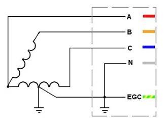
Schematically, it looks like this:
3 Phase open delta power
Regular 3 phase delta looks like this:
3 phase delta power
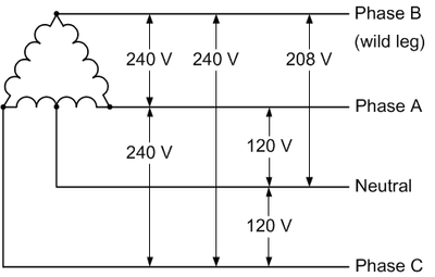
Most utility companies will not hook up 3 phase delta on the customer side anymore because the “high” or “wild” leg, which as shown in the diagram runs a good deal higher than 120 volts to neutral. Hook up a high leg to a single phase 120 volt piece of equipment and wait for the power supply to blow up. Also true with 277-volt lighting circuits, as my assistant once found out with the Coke Machine in the break room. The new 3 phase service will almost invariably be 208 wye unless there is some very compelling reason, which is fine.
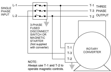
There are many ways to get around three phase open delta, perhaps the best is a rotary phase converter. This piece of equipment will take a 240-volt split phase and add a third leg. These legs will not be 120 degrees apart, as they would be in a true three-phase, however, they will be close enough that 3 phase motors and transformers will be happy.
Rotary Phase converter
This leads to an unbalanced voltage/current condition which needs to be accounted for in the design of the unit. The second way to do this is to power a three-phase generator with a split-phase motor. This will completely isolate the 3 phase equipment from the utility service and provide for true three phase power.
The downside to any motor/generator or rotary converter is moving parts and conversion inefficiencies. At any transmitter site that uses this type of equipment, either a backup power converter or a lower power split phase backup transmitter should be installed. With all mechanical things, eventually, this will need to be repaired and it would suck to be off the air while that is happening.
Regardless of any of that, this particular service is about to be disconnected permanently. Good riddance.
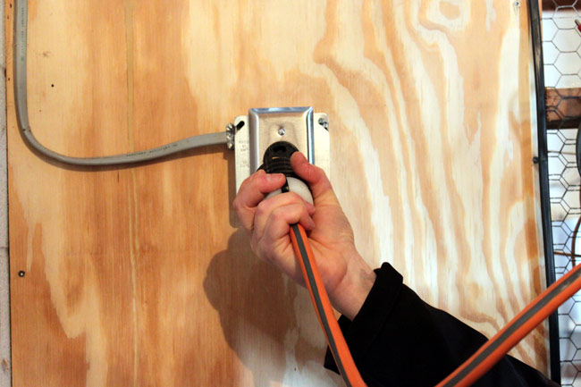
Sometimes there is just no way around it, especially with some modern equipment:
Hard restart, Nautel VS2500 transmitter
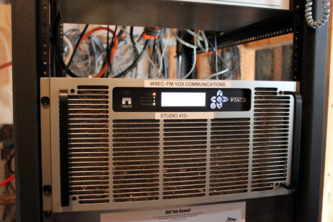
This Nautel VS2500 transmitter got all cranky after lightning struck the tower (or nearby) on Friday night. Thunderstorms in February are not unheard of, but they are unusual, at least in the Northeastern United States.
Nautel VS2500 FM transmitter, WBEC-FM, Pittsfield, MA
Anyway, the transmitter would not reset or restart via remote control, therefore, we had to ride the chair lift to the top of the hill and pull the plug to reset its logic and start over again.
Bousquet Ski Area Chair lift
At least the trip up to the transmitter site was scenic. We had to wait a day for the winds to calm down, but all in all, not a terrible day. Did I mention the scenery?