Good troubleshooters are becoming rare these days. To some, the idea of working through a problem, finding and then fixing an issue seems like a time-consuming, wasteful evolution. More often than not, it is easier to replace the entire assembly with a new one, throwing the old one away. This is especially true with computer components. The other option is to send a module or assembly back to the factory for repair. Truth be told, often that is a good course of action when a fully equipped repair bench is not available. Surface mount technology can be difficult to repair in the field, as can many RF components.
Being able to troubleshoot components and assemblies is still a valuable skill. Finding and identifying trouble is a good skill no matter what it is used for. I find analytical troubleshooting skills to be good life skills to have. I think my in-laws are occasionally amazed when I walk into a situation and point to something and say: There it is, fix that.
Coil burned out on 40 amp RF contactor
Many times, however, there is no smoking gun. Those situations require a bit of investigative work. The first step in troubleshooting is developing a history:
Has this failed before
Is there a history of failures
Has it been worked on recently
Is it new
Has it been installed properly
It is old
Has it been affected by some outside force like lightning or a power surge
This is where good maintenance records or maintenance logs come in handy. Recently, I have found many places that lack any type of maintenance documents, which means the repair history is unknown. This makes it difficult to find a good starting point and can greatly increase the amount of time required to troubleshoot a problem.
Once the pertinent history is gathered, it can be organized and analyzed for clues. For example, if something has been worked on recently, that is a good place to start. If something has a past history of failures, that is a good place to start. Newly installed equipment is subject to early failures under warranty due to component failures. Old equipment may just be plumb-worn out. Improperly installed equipment can exhibit all kinds of bizarre failure modes. That information coupled with known symptoms would indicate a good starting point for troubleshooting the problem.
If no good starting point can be discerned, then the next step is to recreate the failure. This usually means turning the thing back on to see what it does. Chances are good that whatever the problem is, it will still be there. Once a good set of symptoms have been identified, then it is time to start working at one end of the problem unit once the failed component is isolated.
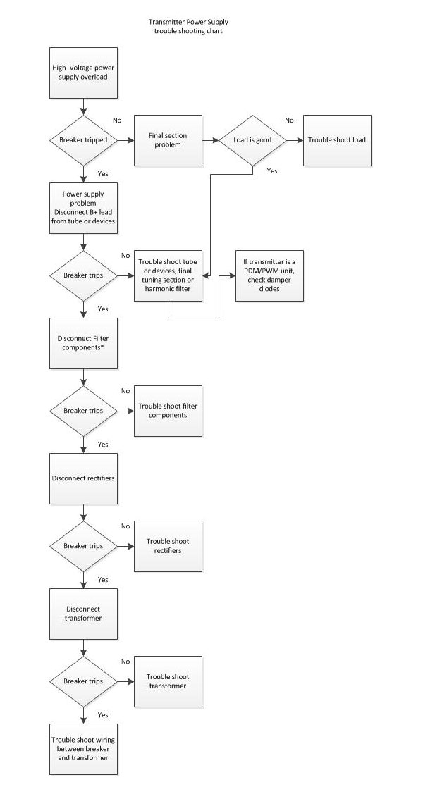
Oftentimes, equipment manuals will have troubleshooting guides. These can greatly speed up the process for large, complicated things like transmitters, generators, and so on. There is also the tried and true troubleshooting chart:
Generic transmitter power supply trouble shooting chart
This is an example of a troubleshooting chart for a transmitter power supply. Many equipment manuals will have this type of information in the maintenance sections.
It is also important to note that when working on high-voltage systems, it is necessary to have two persons on-site at all times.
Good troubleshooting skills have many applications.
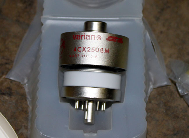
It’s a cute little thing. These were often used for driver tubes in FM broadcast transmitters. With the naming conventions of ceramic tubes, we can tell quite a bit about the unit without even looking at the datasheet.
The first number indicates the number of grids in the tube, 3 makes it a triode, 4 tetrode, and 5 pentode.
The C means it is a ceramic tube
The X indicates it is air cooled, a V is vapor cooled, W is water cooled, M is multiphase
The 250 is the plate dissipation is watts
B is the design revision.
Thus a 4CV100,000 is a vapor-cooled tube capable of dissipating 100,000 watts, something one might find in a high-powered MF or HF transmitter.
Other bits of critical information about tubes would be maximum plate voltage, maximum screen voltage, maximum grid voltage, maximum screen dissipation, maximum grid dissipation, and filament voltage. Something to keep in mind when tuning a transmitter.
This particular tube is installed in the driver section of a Continental 816R2 transmitter.
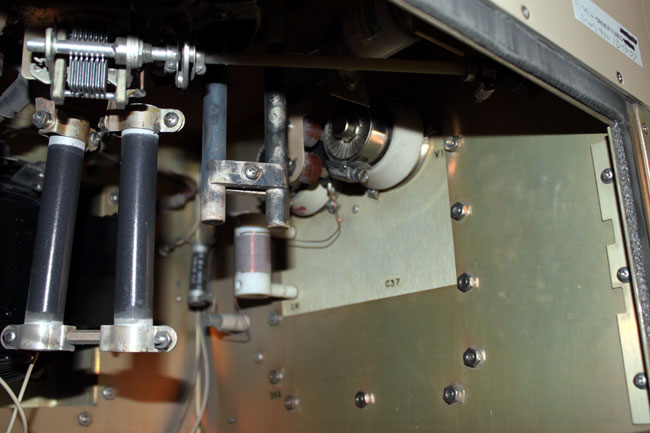
Continental 816R2 driver section
I have noticed that these tubes have a much shorter life than there predecessors. Back ten or twenty years ago, they usually lasted 12-14 months. The latest set lasted only 8 months and both units failed catastrophically. That points to one of two things; either something in the transmitter has changed or something in the way the tubes are manufactured has changed. Once the new tubes were installed, I checked all of the parameters against previous maintenance logs. I also checked things like air flow, dirt and other possible culprits.
I could find no changes in the transmitter. The only thing I can think of is the fact that the tubes are installed horizontally, which causes the elements to warp and eventually break or short.
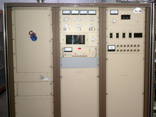
Continental 816R2 transmitter, WFLY, Troy, NY
I am thinking we may try to convert the driver section of this transmitter to a solid state unit. The transmitter itself is 24 years old, but is still works and sounds great. I’d hate to get rid of it because of its driver section.
Perhaps it is a good time to pose a few questions regarding the future of radio broadcasting and digital radio in particular. For this article, I will assume that everyone understands that digital radio is a type of modulation using data transmitted at high speeds, which is reassembled in the receiver to generate audio for the listener.
Why is digital radio needed?
What are the benefits of transitioning to digital radio?
Who would benefit most?
Who would benefit the least?
What are the alternatives to digital radio?
Why or why not proceed with the transition already started?
To answer the first question, we need to understand the current consumer marketplace and the all-pervasive notion of disruptive (aka destructive) innovation. That is to say, a new technology that builds on existing technology or knowledge, while eventually replacing or destroying its predecessor. Think; horse and buggy vs. automobile, microwave network vs. fiber optic network, wired telephone network vs. cellular phones or film photography vs digital photography. In other words, the older technology becomes obsolete and is abandoned in view of the improvements brought on by innovations.
Disruptive Technology
No one can argue that innovations have not greatly improved our lifestyle and productivity in the last one hundred years. Few would opt to permanently return to an era of no electricity, no electronic communications, and no cars. In order for the destructive innovation argument to succeed, however, the technology in question must be improved in a way that benefits the greater society.
Digital modulation methods have been under development since ATT started using T-carriers to transmit telephone calls over long-distance circuits. Over the years, several different methods were developed including Phase (or Frequency) Shift Keying (PSK), Multiple Phase Shift Keying (QPSK), Quadrature Amplitude Modulation (QAM), and Orthogonal Frequency Division Multiplexing (ODFM).
For various purposes, these digital modulation methods offer distinct advantages over analog modulation methods.
Thus, the proponents of digital radio broadcasting postulate the advantages of transitioning to digital radio are:
Improved sound quality, often using terms like “CD Quality,” etc
Improved spectrum efficiency, more broadcasting channels for the same amount of frequency allotted.
Improved coverage area, less interference, out-of-band noise, etc
Value-added accessories, such as data services (song title and artist), album art, Electronic Programming Guide, H. 264 video, etc
Keep up with evolving technology
Thus, the question of why digital radio is needed is answered by listing the possible benefits of such a transition. By the list of benefits above, most consumers would find improvements in digital radio broadcasting as would most broadcasters. In theory, it is not a bad idea.
In the real world, theory, and application are often radically different. Innovation is most often, although not always, driven by a profit motive. Digital radio technology is no different. The proponents of digital radio are attempting to move technology forward while making a profit. There is nothing wrong with that, provided the consumer sees the value in the new technology and embraces it. That is a key part of the current digital radio puzzle which is missing; the consumer.
Unfortunately for digital radio broadcasting, several of the above benefits have not been fully realized in the first iteration of the technology. In several countries, digital radio has taken the form of IBOC via either DRM or HD Radio®. Others choose to do DAB via Eureka 147. In almost every case, the average consumer has not embraced the new technology for several reasons:
Coincidentally with the rollout of IBOC, the mobile internet has become pervasive through the use of things like smartphones, tablets, and similar devices. Via 3G and 4G mobile networks, consumers can access almost an unlimited number of programming choices from across the world.
Programming offerings on digital radio differ only slightly from those available on analog radio. Consumers are left with no compelling reason to purchase or install a digital radio.
The technical advantages of digital radio are not consistent enough or significant enough to make a difference in the listening experience.
The availability of other competing entertainment mediums such as MP3 players, satellite radio (XM/Sirius), internet streaming, etc.
Many point out that internet-type services require an internet service provider (ISP), mobile data plans, or some other type of paid service. Further; 3G, 4G, and or WiFi services are not universally available. All of that may be true, however, mobile data networks are rolling out far faster than IBOC. Consumers appear to be willing to pay for internet service for a variety of reasons, including mobile listening.
The major flaw of internet technology is the capability of ISPs to cut off service at the request of the government for any reason. There is also the ability to block access to certain websites, countries, search results, or services. There are several bills currently under consideration in Congress to codify this, which is an ominous development. Eventually, one of these bills will make it through and become law, creating some form of censorship on the internet. In light of the potential issues with the internet, free, over-the-air broadcasting is necessary, if not vital, to democracy provided the ownership is dispersed and diverse.
There are distinct advantages to digital radio broadcasting which may be realized with different systems that are developed in the future. It may require a re-think of what it means to be a broadcaster and how to make digital radio broadcasting more like IP-based interactive web streaming, available for free using different frequencies than what is in use currently. The general public has shown, by their lack of interest, that digital radio broadcasting as is being carried out today is not necessary. While digital modulation has been around for quite some time, the politics and bureaucracy involved with creating a digital radio broadcasting service has stunted development, making the technology almost irrelevant.
So sent wireless operator John “Jack” Phillips on the night of April 14th, 1912, and likely sealed the fate of some 1,514 passengers and crew of the RMS Titanic, radio call sign MGY. That message was sent in response to the radio operator on the SS Californian/MWL, who was attempting to report icebergs nearby.
RMS Titanic side view
Of course, it would be a gross error to blame the sinking of the Titanic on the radio operator, he was but one small link in a long chain of events that unwound that fateful night one hundred years ago. Beginning with the ship’s design and ending with the Captain of the Titanic, Edward Smith, many seemingly unconnected decisions lead up to the ultimate disaster that befell the Titanic.
After about four days at sea, during the late morning/early afternoon of April 14th, the Titanic began receiving wireless messages indicating “growlers, bergs, and ice fields” were in the area. The Captain decided to alter the ship’s course to the south, out of the supposed ice fields.
In spite of numerous reports of nearby ice, the Captain did not order the ship to reduce speed. It continued on at 22 knots (41 kp/h) up until the time it struck the berg. Lookouts were posted in the crow’s nest, near the bow, to spot icebergs. This was considered normal operating procedure at the time but is the most significant factor in the collision. A number of nearby ships had spotted ice and had greatly reduced speed or stopped for the night. Further exacerbating the situation, the lookouts on the Titanic did not have binoculars, which was due to a mix-up before they sailed from England.
Some of the ice reports received later in the day and evening did not make it to the bridge. Wireless operator Jack Phillips was either repairing a malfunctioning spark gap transmitter or was sending messages from passengers to Cape Race Radio/MCE, Newfoundland. At the time, the (wireless) radio operators were not a part of ship’s company but rather were employed by the Marconi Company for the purpose of sending messages for profit. Any notion of safety or distress communication was an afterthought.
The SS Californian, the closest ship to the Titanic at the time it sunk, was attempting to broadcast another ice warning to all ships in the area at about 10:30 pm. The message was broken off by Phillips with a terse: “SHUT UP! SHUT UP! I AM WORKING CAPE RACE” At about 11:30 pm, Cyril Evans, the Californian radio operator closed the station and went to bed. Ten minutes later, the Titanic struck the iceberg.
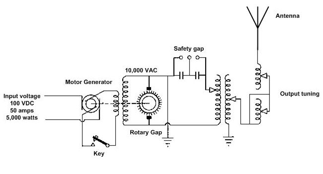
5 KW synchronous rotary spark gap transmitter
The Titanic used a 5 KW synchronous rotary spark gap transmitter, which was state of the art at the time. The power is measured at the input of the DC motor. Considering the efficiencies of the motor and generator, the ability of the spark gap to generate RF, and the efficiency of the tuning circuits and antenna, the actual power radiated by the transmitting antenna would have been significantly less, on the order of a couple of hundred watts. The above schematic is not exactly the same as the unit installed on the Titanic, as the meters and additional controls for motor speed and generator voltage have been omitted. Additionally, some sources report the transmitter as a 1.5 KW non-synchronous unit. The difference between the two would be very apparent in the sound of the received signal; a synchronous transmitter had a tonal quality to it versus a non-synchronous or simple spark gap, which sounded like hissing. Wireless operators from shore stations and other ships who worked the Titanic reported that they were using a synchronous unit.
The transmitter used two frequencies; 600 meters, or 500 KHz, and 300 meters, or 1,000 KHz. Because of these frequencies, the maximum range during daylight hours was about 200-400 miles (322-644 km). At night, the ranges were considerably more, 1,000-2,000 miles (1600-3200 km), which is typical for medium frequencies, including the AM or standard broadcast band in use today. Thus the effort by the Titanic radio operators to clear the backlog of message traffic during darkness, when Cape Race was about 374 miles (602 km) away.
Another part of the problem was with the transmitting and receiving apparatus itself. The transmitters were crude and generated broad harsh signals. The receivers were also very broad, and nearby transmitting stations could easily wipe out all frequencies on early receivers. That is what likely prompted Phillips’ outburst, something termed today as blanketing interference. Vacuum tubes (aka valves) had yet to be accepted for widespread use as amplifiers and most receivers were simple tuned circuits connected to a detector of some type. As such, receivers were far less sensitive and selective than they are today.
Interestingly, the Titanic had both types of receivers on board. The main receiver was a tuned circuit with a Marconi Magnetic detector (aka “Maggie”) and a valve receiver as a backup. The valve or vacuum tube was likely a simple diode detector connected to a tuned circuit.
After the collision, Jack Phillips stayed at his post sending out distress messages and communicating with other ships en route to assist. Long after the Captain told the radio operators they were dismissed, Phillips persisted until power was lost and the radio room began flooding. He perished shortly after in the 28° F (-2°C) water, however, assistant operator, Harold Bride, survived.
There is also some bit of discussion about the rudder commands given after the iceberg was sighted. Most accounts say, First Officer, William Murdoch, gave the command “Hard over starboard” which would be the equivalent of the right full rudder, effectively pushing the back of the ship to the left.
As rudders work, the amount of water flowing over the rudder determines its effectiveness or loading (resistance to water flow). With the center screw turning at full speed, the rudder would have quickly loaded and pushed the rear of the ship away from the center line by re-vectoring the water coming from the propellers. There is no way to know if this would have changed the outcome as not enough is known about the maneuverability of the Titanic. Her sea trials consisted of about seven hours of sailing time before passengers were embarked.
The next commands issued were “full astern,” on the engine room telegraph. Because of the design of the ship, it took about thirty seconds to engage the rudder and backing engines. The ship continued straight ahead at 22 knots (11 meters per second), traveling 372 yards (340 meters) before beginning to turn. The center screw had no reverse, so it was simply stopped. Once the engines were reversed, the rudder lost much of its effectiveness due to turbulent flow and stalling. The ship could not maneuver around the iceberg, striking it in a glancing blow springing the hull plating in five forward compartments on the starboard side.
As it was the Titanic’s maiden voyage, the first officer did not have much deck time and was likely less familiar with the maneuvering characteristics of the ship versus other ships he had conned. On most other ships of the time, including the SS Californian, which had just completed the identical maneuver, that combination of rudder and engine room telegraph commands would have been appropriate to stop and swing the ship around the berg.
The SS Californian was within sight of the Titanic as it sunk, observing several “rockets” (as many as eight) being fired. When informed of the rockets, the Captain of the Californian asked for their color but did not move to investigate or wake the wireless operator. According to some of the Californian bridge crew, the Titanic looked strange in the water, like something was wrong. The Californian attempted to signal the Titanic with a blinking light, which was not acknowledged. Inexplicably, the Californian never attempted to investigate further until 5:30 am the next morning when wireless operator Evans was back on duty and reported the sinking to the bridge.
Therefore, the entire chain of events that led up to the disaster includes:
Too few lifeboats for passengers and crew
Not enough training in the deployment of lifeboats
Very short sea trial period for the ship’s crew before passengers were embarked
Overconfidence in the water-tight door system in keeping the ship afloat
Binoculars for lookouts were not procured in time for sailing
The ship’s rate of speed is too fast for the conditions, with numerous reports of ice in the area
The ship’s radio operator dismissed ice report from the nearest ship (almost within view at the time) so he could continue to send paid message traffic
The combination of helm and engine room telegraph commands did not produce optimum maneuvering
Failure of the nearest ship to recognize distress flares (or rockets) as such and render assistance
Change any one of those nine things and the outcome might be entirely different. Something to ponder.
The result of this disaster was the formal codification of shipboard safety requirements known as SOLAS or Safety Of Life At Sea. Those standards include the transmission of distress signals, distress communications, numbers of lifeboats, radio watches, fire suppression systems, and training for passengers and crew. Currently, the distress communication system is known as the Global Maritime Distress Safety System or GMDSS.