It they don’t care all that much about traditional phone service anymore. Through attrition, they have reduced their tech workforce to about half what it was 15 years ago. All of the infrastructure; overhead cables, buried cables, office frames, switching equipment, is getting old. Some of the cabling around here, both buried and overhead, is the original stuff, installed 100 years ago. Because it is expensive to replace, they don’t want to change it out, opting to simply limp along, swapping out pairs when a line or circuit goes dead.
I will be surprised if the traditional wired telephone network still exists in ten years. Think about it, ten years ago were just heaving a collective sigh of relief that Y2K turned out to be nothing, remember that?
For the local phone giant, offering 3 in one (telephone service, internet service, and cable TV) is more appealing than servicing their existing accounts, including HICAP (high capacity) data circuits like T-1, BRI&PRI ISDN, etc. Much less so for a POTS line, which, good luck if you really need it fixed right away, we’ll be over when we get to it, just keep your paints on mister.
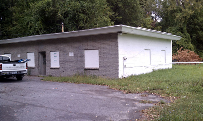
I’ve written about this before. A particular station for my former employer uses a T-1 circuit to relay the program from the studio to the transmitter site. This is fairly common in larger metropolitan areas where 950 Mhz STL frequencies are not available, nor is a line of sight between the studio and transmitter site obtainable.
Back in 2002, when the company was in the process of acquiring said station, I recommended a 950 Mhz STL. There was an existing STL license, fully coordinated, that came with the main station license. Only the equipment was needed. No, I was told by the CFO, we will do a T-1, thank you very much. I argued my point, saying that putting our radio station exclusively in the hands of the phone company was a bad idea. We would have problems with outages and service. No, said the CFO, this is New York, all the radio stations do that. Not exactly, New York is about 15 miles SOUTH of here, this is Westchester, the cables are old, and a lot of them are overhead, which exposes them to lightning, vehicle damage, water, etc. There will be service issues if we rely solely on a T-1.
No, he said, “We are using a T-1 and that is final.” I hate to say I told you so, but… Let us examine the history between then and now:
| Date of outage | Date of restoration | Total days |
| April 5, 2004 | April 9, 2004 | 4 |
| September 8, 2006 | September 10, 2006 | 2 |
| May 2, 2007 | May 5, 2007 | 3 |
| August 27, 2009 | September 4, 2009 | 10 |
| September 5, 2010 | September 15, 2010 | 10 |
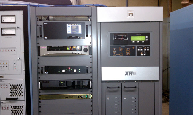
Fortunately, I wrote all this down in the transmitter site log. I was able to check it yesterday when I went to restore the station to normal operation after the latest T-1 failure.
During those periods, we used BRI-ISDN, which is okay but it carried the same phone cable. It is likely to go down if there is a major cable interruption. We have installed a second T-1 circuit, which fails when the other T-1 circuit fails. We have used 3G wireless sprint card and streamed audio from the internet. That didn’t sound great, but we did clear inventory. We have moved one of the AudioVault servers to the transmitter site, and updated it once a day via the shoe leather network, that sounded great, but it was difficult to do. We have borrowed an ethernet connection from another tower site tenant onsite and streamed internet audio via a wired connection, which sounds pretty good.
Still, the best thing to do would be to establish our own STL path to the transmitter and get rid of the T-1 lines.
The Problem with the Phone Company is they are not all that interested in simple copper circuits anymore. Now, there is something called FiOS, which, it would appear is a much better profit center than ordinary copper circuits.