What is “Phasing” as it relates to radio?

Occasional reader Jeffery asks a good question, which I will attempt to answer here in simple terms. Phasing, when used with antennas, refers to the relationship that two or more radiating elements share with the waveform being transmitted.  It is used to create an RF radiation pattern by adding energy to the wavefront in one direction by taking energy away from the wavefront in another direction.

Phasing is often described as +/- X number of degrees from a reference point.  Graphically, it would look like this:

One wavelength with +/- 180 degrees notated

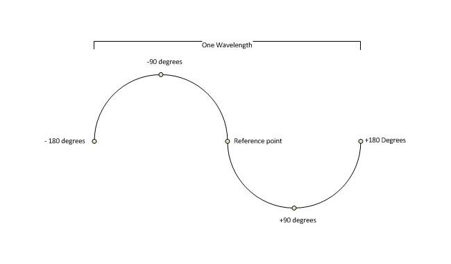
The reference point can be changed to any point on the waveform, in radio applications it is usually oriented around +/- 180 degrees.  If the reference point is a single tower or element then this would be the end of the story. Add a second tower to this system and it would look something like this:

Double wave form
Double waveform

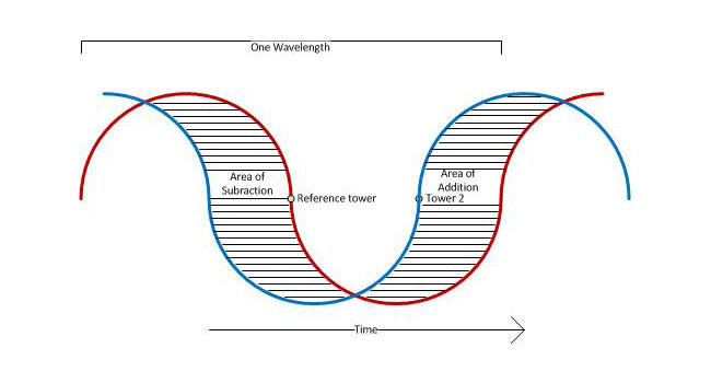
In this picture we have two waves being radiated from two separate elements. These elements are spaced 100 degrees apart and tower #2 is phased to +90 degrees.  RF generator is coupled to both towers via a power divider, the reference tower (tower #1) is feed with 57% of the power that tower #2 is being feed.  Thus, the ratio of power to the respective towers would be 57:42.  Thus, if tower one had a power reading of 1.00, tower two would be 0.74.  The towers are on a north/south line with the reference tower bearing 180° from tower #2.  In the area of subtraction, the waveforms from each tower cancel each other out to some radiating less power toward the south; in the area of addition, the waveforms sum to create a more powerful waveform, radiating more power towards the north.

Resulting pattern (WKIP, Poughkeepsie, NY):

WKIP 1450 Poughkeepsie, NY pattern plot

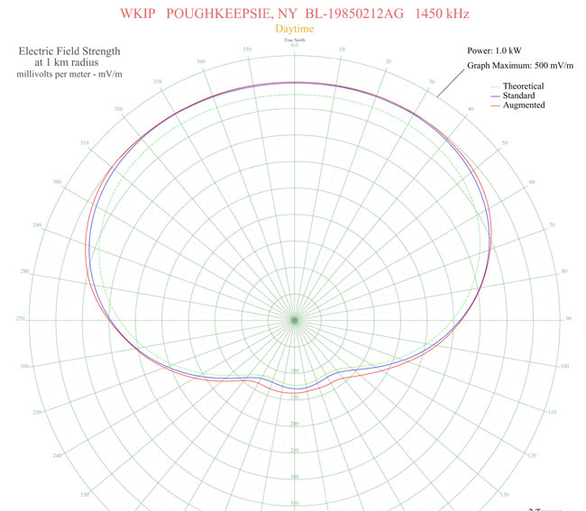
This is a typical two tower array, however, there are two slight differences; the reference tower is 215 degrees tall, tower two is 90 degrees tall. This is yet another use of “degrees” to relate electrical length or separations. The second, more notable distinction is that this array is Directional daytime, and non-directional night time, which is the opposite of most AM stations in this country.

Electrical height can also be described as a function of wave length, e.g. 1/4 wave, 1/2 wave, etc.  Most AM towers in this country are 1/4 wave length, which equates to 90 degrees.  Often, higher powered stations, and some low powered stations put up towers near 1/2 wavelength due to the better ground wave performance of those towers.  At lower dial positions, a 1/2 wave tower becomes an expensive proposition due to the height required.

In theory, an unlimited number of towers can be used to create a pattern by introducing nulls (areas of subtraction) and lobes (areas of addition).  In practice, the highest number of towers I’ve ever heard being used in an AM directional array is twelve; KFXR 1190, Dallas, TX.  There may be others, too.

An excellent resource for AM directional antenna technical information is Jack Layton’s Directional Antennas Made Simple, which is out of print but available from various sources.

Hot Elbow

Found this 3-inch rigid elbow to be a little warm when we were removing a dividing wall as a part of an AC upgrade:

MYAT 3 inch elbow
MYAT 3 inch elbow

As measured with my Fluke 62 mini IR thermometer, the temperature is 163°F (72.7°C) at the clamp and drops down in both directions.

This is at WEBE and this particular section of the transmission line is running 34 KW into the analog/digital combiner in the next room.  The clamps are tight, but you can see a little scorch mark on the stainless steel clamp right over the slot in the field flange.  That is where there is a gap between the outer conductors, which possibly means the inner conductor was cut slightly too long during installation.  I suspect this and or a problem with the bullet is causing the heating issue.  I was never (and still am not) a fan of those field flange-type elbows, I’d much prefer the flanged type with a field flange on the straight line section.

34 KW is getting into the semi-serious power level for FM broadcasting.  At those levels, even small impedance mismatches can lead to big problems.  We have a new elbow, field flanges, and bullets on order.  Unfortunately, we will have to take the station off the air to replace this.

WEBE transmitter site with partition removed

This is all a part of an air conditioning project. There was a plywood partition wall between the front and the back of the transmitters which was impeding airflow.  All of the HVAC contractors who bid on the AC job identified it as a problem that needed to be addressed before the big 5-ton wall-mount AC units were installed.

Update: Replaced elbow last night (8/4).  Went off at 10 pm and back on at 10:25.  Found the inner conductor had been pushed out of place and was off center on the outside (toward the wall side) of the elbow.  This was an older elbow that did not have the nylon inner spacers on the center conductor.  The inner conductor was dark purple.  Before replacement, the elbow was 138°F (59°C) under full power (34 KW).  After replacement, it was 97°F (36°C) as was the rest of the transmission line.  At these power levels and frequencies, even small, minor imperfections cause impedance shifts and become issues.

Myat 3 1/8 inch elbow

I cleaned up and reused the bullets and the outer conductor with scotch brite. I also used more support wires because I believe the elbow was starting to pull apart, which can sort of be seen in the first picture.

The Onan RS-15000 Generator

It is a cute little thing. This one is being installed at a mountaintop transmitter site for a class A WKIP-FM in Ellenville, NY.  It is way up in the air (at least by local standards) at 2,450 feet AMSL.  As such, the TPO is only 300 watts into a one-bay antenna.  Therefore, even this little generator will be loafing along.  I added all the rack equipment up, both transmitters (main and backup), and the electric resistance heater and came up with a grand total of 6,300 watts.  The working load today was 3,200 watts, which I would assume is about average.

Onan RS-15000 at transmitter site with ice shield

Denis, my sometimes helper, build an ice shield over the top of the unit with pressure-treated wood.  This unit was placed about 40 feet away from the 140-foot tower, next to the concrete block building.  Still, on a windy day, I could see some chunks of ice flying off the tower in this direction.

It has a Lister/Petter 1900 cc engine, 1800 RPM, 240-volt split phase generator.  At 25% load, it burns 1.2 gallons of propane per hour.

Onan RS-15000 gaseous generator

This is annoying. The gas installer blocked access to one of the through holes in the bottom of the enclosure frame. Actually, more than annoying, downright annoying as it blocked the exact center of the hole.  I had to move the regulator up about two inches so I could run the 1-inch flex under the gas line.  This, in turn, led to some amount of swearing.

Gas supply to generator installed by selfish gas man
Gas supply to a generator installed by selfish gas man or woman

Another side of the engine:

Lister petter 4 cylinder 1900 cc engine
Lister Petter 4 cylinder 1900 cc engine

Pushrods going to rocker’s arms over the cylinders.  Low-tech, under-head cam engine. That’s okay, so long as it works when it is supposed to.

Onan RS-15000 generator wired to transmitter building
Onan RS-15000 generator wired to the transmitter building

PVC conduit running into the transfer switch.  The final connection is made with a liquid-tight flexible metal conduit (FMC).  The control wiring is run in a separate 1/2-inch conduit, as required by NEC.

AM radio sucks! It’s horrible, sounds terrible and should be turned off!

This is a youtube video of a Police song from the 1980s received via skywave and recorded off-air on an AM radio.

Video Description:

The classic 1983 #1 smash hit, as received in analog C-Quam AM Stereo… in Japan… via nighttime skywave in the Tokyo area, roughly 500 miles away from Sapporo (ed: where the station is located). The audio quality is among the best I’ve ever heard from analog AM radio, thanks in large part to an excellent wideband receiver, very quiet band conditions, and the Orban Optimod-AM 9100 audio processor being used by HBC Radio to its maximum extent: 12.5 kHz audio bandwidth with stereo enhancement added (above and beyond the amount naturally provided by the matrix processing used by AM Stereo).

Absolute trash, I tell you. Just awful.

Of course, I know several FM stations around here that wished they sounded as good. Naturally, Japan, they have sought to minimize night-time interference problems by limiting the number of stations on the air and enforcing the rules and regulations in place to protect those stations on the air. They also seem to allow greater bandwidth, out to 12.5 KHz in spite of the narrower channel allocations (9 KHz in ITU regions I and III, vs 10 KHz here in the US, ITU region II). One other thing to note, there is no digital buzz saw occupying several channels of the broadcast spectrum. Keep in mind, this was received in Tokyo, likely a very high noise environment.

I was trying to find out the power level of the transmitter, the call sign is JOHR in Sapporo Japan, frequency is 1287 KHz. HBC is the Hokkaido Broadcasting Company, a privately held company. The state-run radio outlets in Japan are NHK, which has several radio and TV stations throughout the islands.

Anyway, AM is dead. Killed by the very owners of the broadcasting companies themselves with help from the NAB. They are the ones that petitioned the FCC to loosen up the allocations and allow more and more stations to be crammed into the band. That is old news. The new news is same forces that killed AM radio are diligently working their magic on the FM band as well. More stations, translators, digital IBOC nonsense that doesn’t work, more of everything. After all, more is better. Until it is not. Then it’s too late.