RoHS and Electronics Reliability

ROHS stands for Restriction of Hazardous Substances Directive. It is a mainly European effort to reduce lead (Pb), Mercury (Hg), Cadmium (Cd), Hexavalent Chromium (Cr+6), Polybrominated Biphenyl (PBB), Polybrominated diphenyl ethers (PBDE) and Acrylamide in electronics and consumer goods.

The main effort appears to be in the reduction of lead in circuit boards and solder.  Generally speaking, the reduction of pollutants is a good thing.  Lead is toxic, especially to young children. Mercury is a potent neurotoxin.  Those other elements and chemicals don’t sound good either.

There are all sorts of green logos and other nice-looking things attached to products that meet the standard.

Typical ROHS label
Typical ROHS label

I feel better, don’t you?

Now for the other side of ROHS.  According to Lead Free Electronics Reliability (large .pdf) by Dr. Andrew Kostic, the effort had been hugely expensive with very limited results:

A huge (~ $14B annual revenue) semiconductor manufacturer estimated the annual worldwide Pb reduction per 1,000,000,000 integrated circuits was only equivalent to ~100 automobile batteries.

Wow!  That is simply amazing on the face of it.  Over the years, I have probably found and carted at least 10 old car batteries to the recycling center for a few dollars each.  According to the Kostic paper:

(Computer chip manufacturer) Intel’s efforts to remove lead from its chips have so far cost the company more than $100 million and there is no clear end in sight to the project’s mounting costs

Wouldn’t $100m be better spent on other, more pressing pollution issues?  Fukushima, springs to mind.

Further, the replacement metals used in electronics have some problems of their own.  They may be better for the environment, however, they lack testing and are

Not optimized for high reliability, severe stress, long life applications

Further, replacing parts in legacy equipment using ROHS parts and solder may present problems with bonds between dissimilar metals.  Thus, making field repairs, or any repairs impossible.

Many of the newer solders and circuit boards use Tin (Sn) as the finishing metal.  There is a problem with tin, known as Tin whiskers.  This was first noted at the Bell Labs in 1947.  Small hairs grow out of the surface of the metal, acting as short circuits, and at higher (above 6 GHz) frequency RF, antennas.   This happens with other metals such as Zinc, Silver, and Gold.

Silver Sulfide Whiskers on circuit board

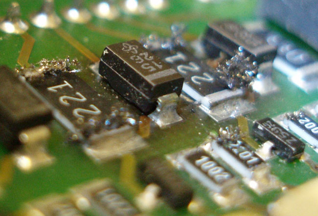
As you can probably deduce, this can have certain detrimental effects on the performance of the circuits in question.  I can imagine all sorts of strange behavior from controllers and other bits and parts of equipment.

I don’t know how prevalent this is in Europe where the directive has been in effect for 6 years or so.  It would be interesting to find out.  I also wonder how many US manufacturers are adopting RoHS as the de facto standard in order to do business in Europe.

The Harris Z6HD transmitter

These transmitters are good.   They seem to behave in a mostly normal manner, having a few quirks now and then. This particular unit is installed at WFAS-FM in White Plains NY.

Harrsi Z6HD transmitter, WFAS-FM, White Plains, NY

I believe the reason for the installation was for the HD Radio® that was in it.  The Deathstar HD Radio® exciter is in the next rack over.  No further comment is needed.

On this day, the transmitter had given up, throwing a main fan fault.  The fan (blower) motor had been replaced in the last six months (on a transmitter that is only five years old), so it was not that.  As it turns out, the stock fuses; 10 amp, slow blow, were just a little bit underrated for the job.  Harris released a service bulletin a few years ago calling for 15 amp slow blow fuses as replacements.  In any case, it was an easy fix and now there is a box of 15 amp slow blow fuses in the transmitter next to the fuse holders.

Harris Z6HD transmitter front RF modules

The modules are accessible by the front and rear of the transmitter.  These doors can be opened with the unit on the air since all of the high voltage is in the bottom of the transmitter where the blower is located.

The module in the middle is the IPA.  Each module has two RF amps, and each RF amp has two devices (BLF-177).  The devices are field replaceable, however, on the HD models, one has to make sure that the amplifiers are still linear.  On the non-HD models (Z6CD), this is not a problem at all.  Shorted MOSFETS will be noted by a fault of one entire power supply.  Removing the bad RF module will allow the transmitter to run at somewhat reduced power.  Finding the bad module may take a bit of trial and error.

Harris Z6HD transmitter back

The back of the transmitter has the directional coupler, low pass filter, access to the back of the analog exciter, controller, and remote control connection points.

The power supply at the bottom of the transmitter has multiple taps, each one with its own fuse.  These can be a bit of a chore to work on.  There is also a ribbon cable that goes from the controller to the power supply board.  This is directly in the path of the cooling fan and can flop around causing the conductors in the cable to break.  The result is the power supply may not come on or may show an unbalanced power supply condition (in the case of a three-phase transmitter).  Very difficult to diagnose.

Harris Z6HD transmitter, on air, WFAS-FM, White Plains, NY

Here it is, running again.

Lightning season

Here in the northeast, there are seasonal variations in the types of weather phenomena encountered.  Blizzards in the winter, severe thunderstorms, and the occasional tornado in the summer, at least that is the way it normally happens.  This year, we have already had two thunderstorms and a stretch of unusually warm weather.  My highly advanced personal weather prognostication technique consists of looking at trends, and the trend thus far this year is warmer with more storms.

Weather Radar, thunderstorm line

When the weather RADAR looks like this, it is too late.

To that end, it is time to go around and check all of the grounding and lightning suppression methods at various transmitter sites and studios.  I would rather spend a few minutes extra now than get called out in the middle of the night for an off-air emergency related to a lightning strike.

Proper grounding of all equipment, RF cables, and electrical service entrances is the minimum standard for transmitter sites.  Proper grounding means a common point grounding system connected to one ground potential.

To that end, all coaxial cables that enter the building need to have their outer shields bonded to the site grounding system at the base of the tower and the entrance of the building.  With an FM station where the antenna is mounted at the top of a tall tower, the coaxial cable outer jacket acts as an insulator along the length of the tower.  A lightning strike on the tower will induce a very high potential on the outer conductor of an ungrounded transmission line.  After entering the building, the lightning surge will find the next path to ground, which will likely be a coax switch or the transmitter cabinet.  Neither of those two outcomes is desired.

Thus, it was time to ground the transmission lines at WRKI, the FM transmitter we moved last January.

3 inch coaxial cable grounding kit

Fortunately, Andrew, Cablewave, Dielectric, and others make grounding kits for various size coaxial cables. They are very easy to apply and make a solid connection between the outer conductor and the site ground.

3 inch coaxial cable grounding kit

The kit contains a copper band bonded to a ground wire, stainless steel clamp, waterproofing, tape, and a pair of bolts.

3 inch coaxial cable properly grounded

The concept of transmitter site grounding is pretty simple and inexpensive to implement.  Thus, it is surprising to me how many transmitter sites, especially older sites, do not have adequate grounding.  That is an accident waiting to happen.

For more on transmitter site grounding, check Nautel’s publication (.pdf) “Recommendations for Transmitter Site Preparation.”

The old humming console

We are starting to work at a new client’s studios.  It is a bit like stepping into a 1980s time machine, as the newest console seems to be the Broadcast Audio console in the FM studio.  I feel I should wear a wide colorful tie and part my hair in the middle when working there.  There is also an older UMC console in the second production room.

A what?

Exactly.

It seems the UMC console (UMC was a Connecticut-based console manufacturer that was later sold to Broadcast Audio) was having an intermittent hum problem on all the audio buses.

After poking around under the hood for a few minutes, I decided I should begin with the basics.  Checking the power supply for ripple seemed like as good a place to start as any.  This console has a 30-volt and a 12-volt power supply.  The 30-volt supply checked out good, but the 12-volt supply, not so much:

12 volts DC, 2.7 volts AC
12 Volt power supply

2.7 volts AC on the 12-volt DC power supply.  That will put some hum on the audio, all right.  I tried to replace the power supply main filter capacitor, but it had no effect.  The regulator must also be bad and it is a Motorola part number which is likely not made anymore.

12 volt linear power supply

This is a pretty standard off the shelf power supply, I should be able to get one from Mouser for about $60.00 or so for a linear unit, which will be cheaper than us trying to trouble shoot and repair the old one.  In the meantime, I took the 10 amp 0-30 volt bench supply and pressed it into temporary service.  The console is working again, for now.

At some point, all this old, um, stuff needs to be replaced.