FCC rules stipulate that when a station is operating at variance from its licensed parameters for more than 10 days, Special Temporary Authority (STA) is required. The reasons for requesting an STA are varied but could include things like:
- Damaged transmission equipment
- Loss of transmitter site or building use
- Loss of tower
- Eviction
- Facilities upgrade or renovation
- Natural disaster
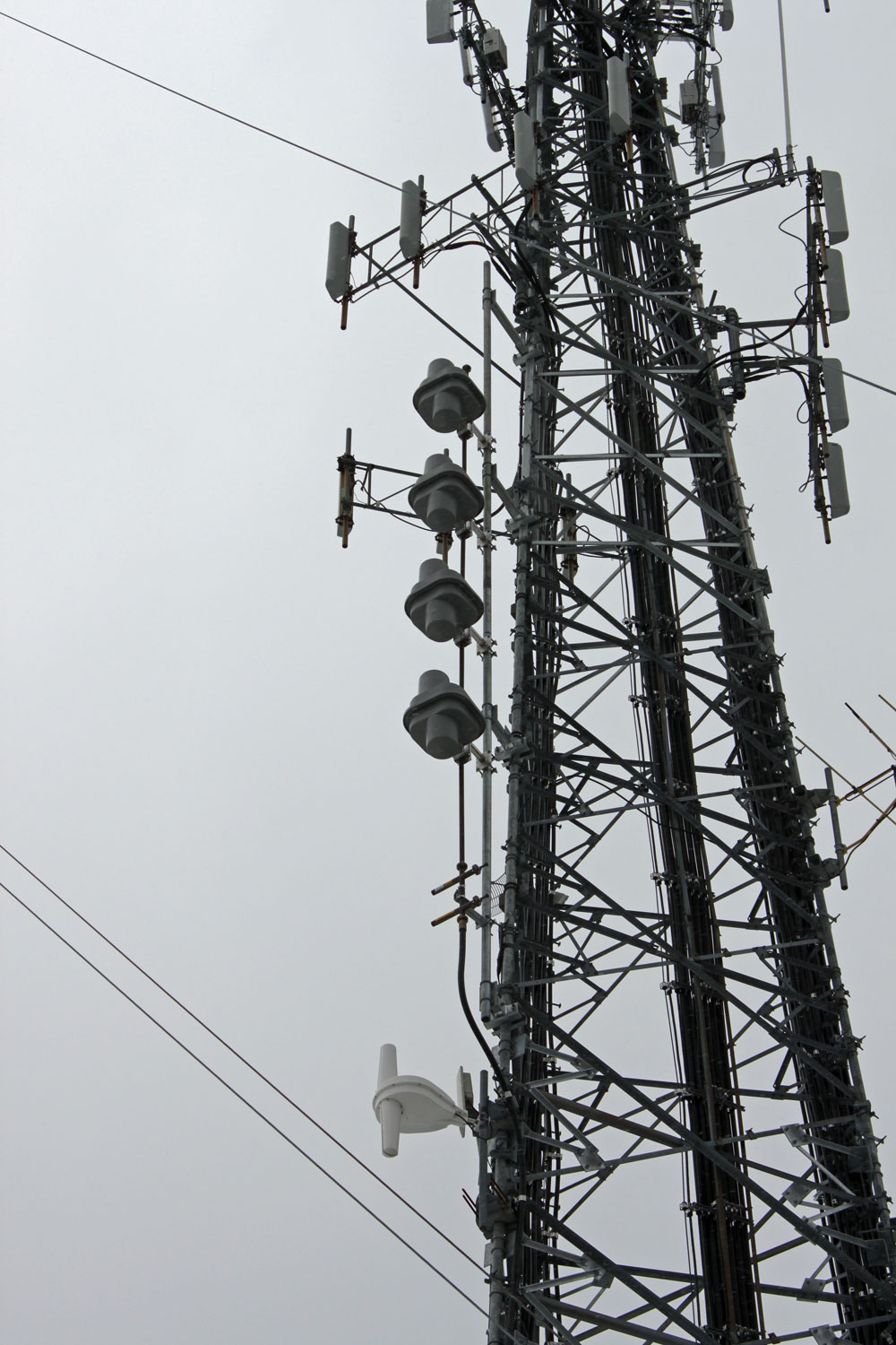
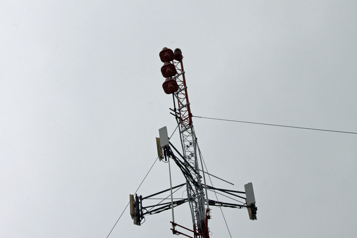
The loss of the transmission tower at WUPE-FM falls into one of those broad categories. Thus, we have filed an STA with the FCC for temporary transmission facilities while a new tower is being constructed. Since the old tower is completely lost, we specified a new tower location, new height above average terrain (HAAT), new ERP, and environmental certification. To gather that information, several steps were needed:
- Obtain a new tower location. This was done with a GPS receiver and verified on itouchmap.com. Once the NAD83 position was obtained, it needed to be converted to NAD27 for the FCC filing. The FCC has a conversion tool on its website.
- HAAT calculation is fairly simple, use the HAAT calculator tool on the FCC website. For this, the antenna radiation center height Above Mean Sea Level (AMSL) is needed. Using a topographical map, find the ground level AMSL, convert it to meters, then add the radiation center height above ground level (AGL).
- The Effective Radiated Power (ERP) calculation is also simple; Transmitter Power Output (TPO) minus system losses (transmission line and antenna gain). It is easiest to do this in dBm, e.g. convert the TPO from Watts to dBm, then add or subtract the gain or losses in dB, and convert the final product back to Watts.
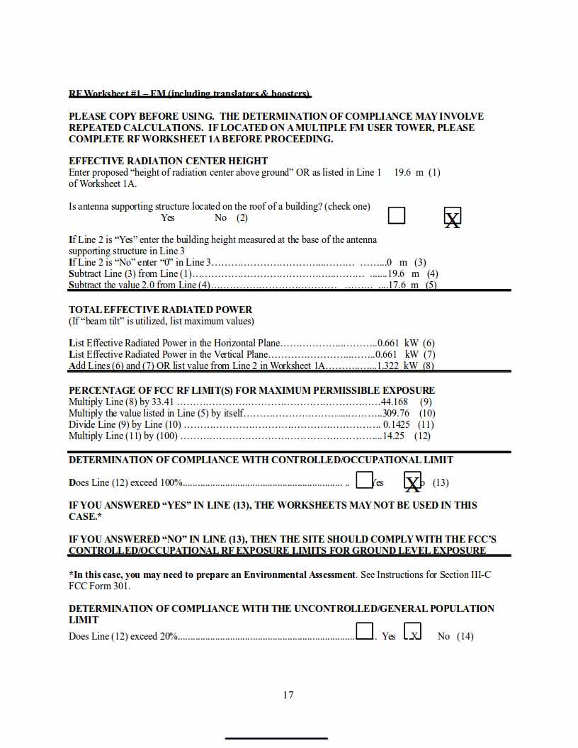
- The environmental statement is slightly more tricky. Basically, the filer is certifying that the STA complies with all environmental regulations including OET-65 (RF exposure limits). Since the temporary antenna is significantly lower than the original, some investigation is required. For this, there are two methods to demonstrate compliance; ground measurements with a NARDA meter, or RFR worksheets which are a part of the broadcast station renewal form, FCC-303s.
I have taken the RF worksheet sections out of the 303s and separated them into the FM RF Worksheet and the AM RF Worksheet. These worksheets are not effective for large tower farm-type sites where there are too many variables and RF contributors to be accounted for. The calculations on the worksheets are not conclusive, however, if the facility in question falls under the limits, it is generally accepted as being in compliance. Taking ground measurements with a NARDA meter is the definitive method for determining RFR compliance. Since this is a relatively simple site, the worksheet calculations should be sufficient.
The worksheet calculations show that the RFR is within both the controlled occupation limits and the uncontrolled general population limits.
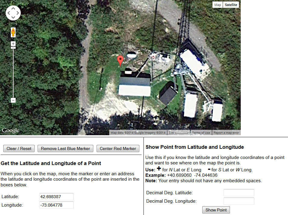
The position of the new temporary pole was verified on itouchmap.com:
It is never good to be operating at a varience from licensed parameters without notification of the FCC. Such things could lead to fine or other problems for the broadcaster.