Most ordinary field engineers will not need to design an ATU in the course of their normal duties. However, knowing the theory behind it can be very helpful when troubleshooting problems. Also, fewer and fewer people understand RF these days, especially when it comes to AM. Knowing a little bit can be an advantage.
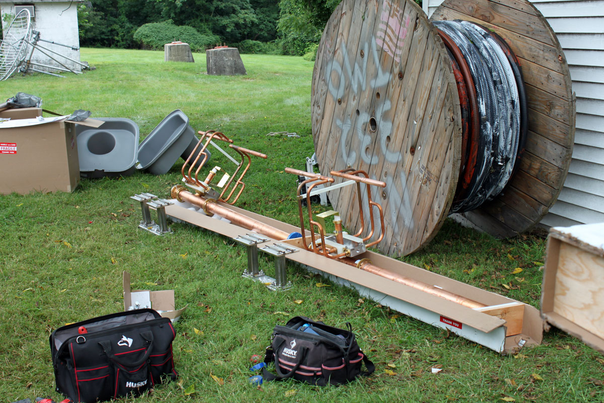
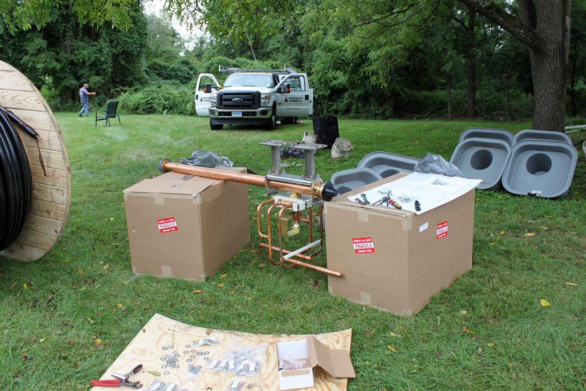
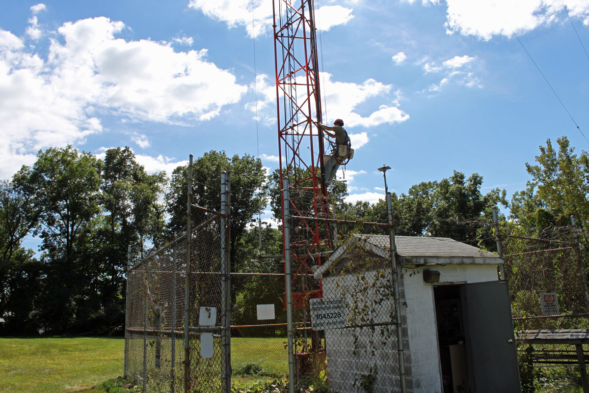
We were working on an AM tower recently when several discrepancies were noted in the ATU:
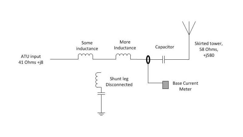
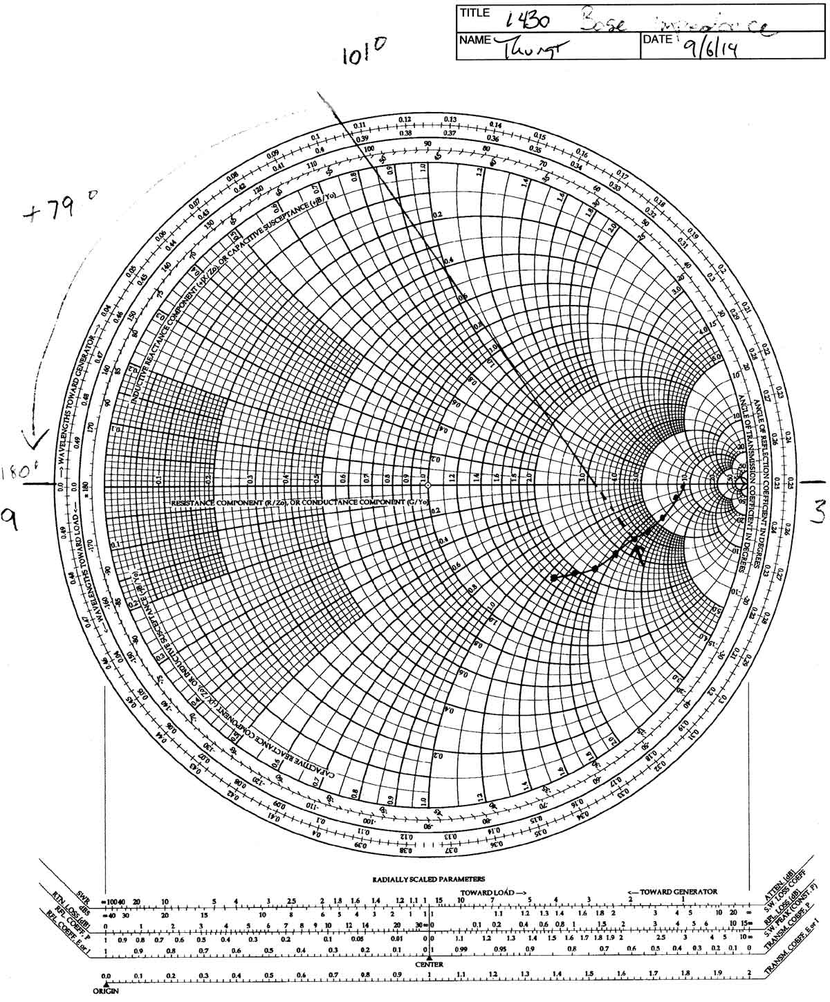
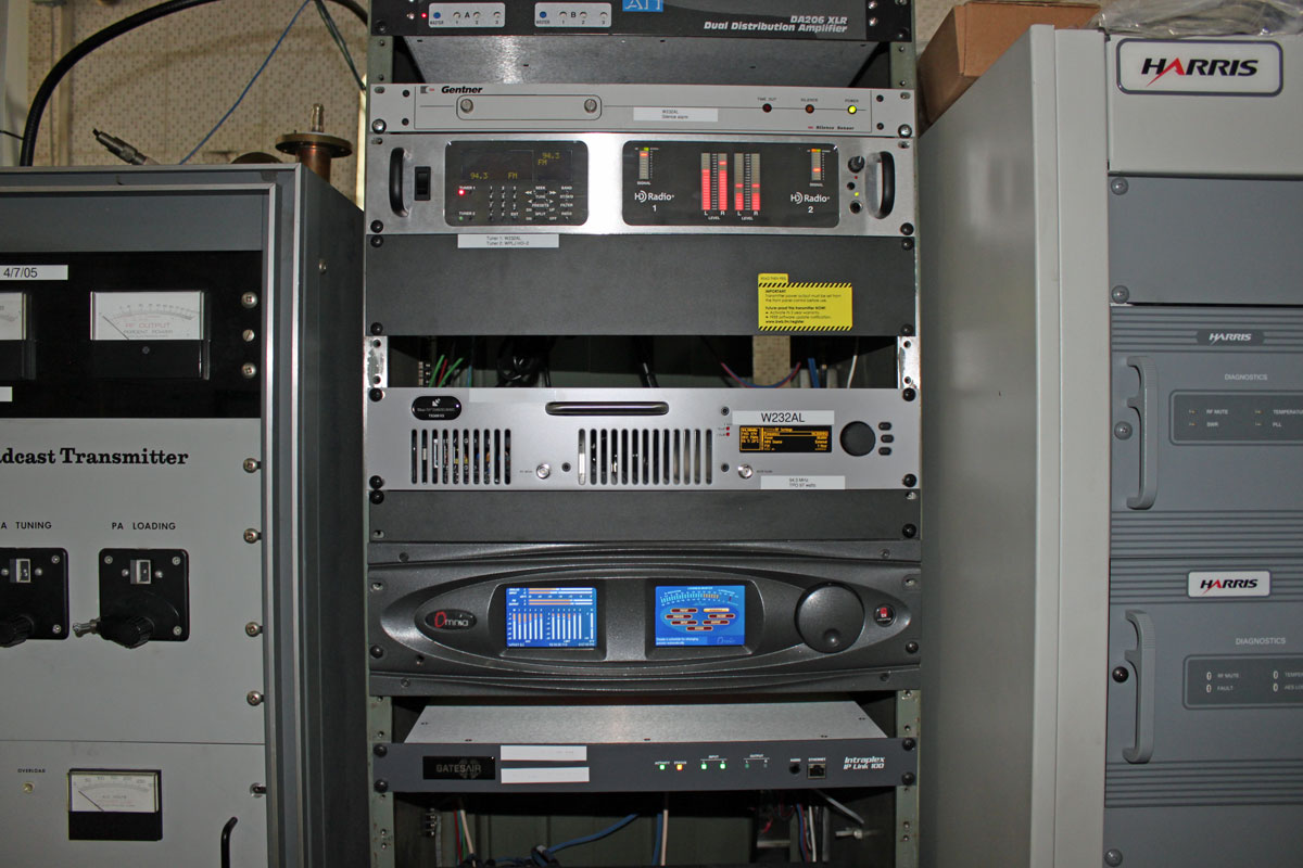
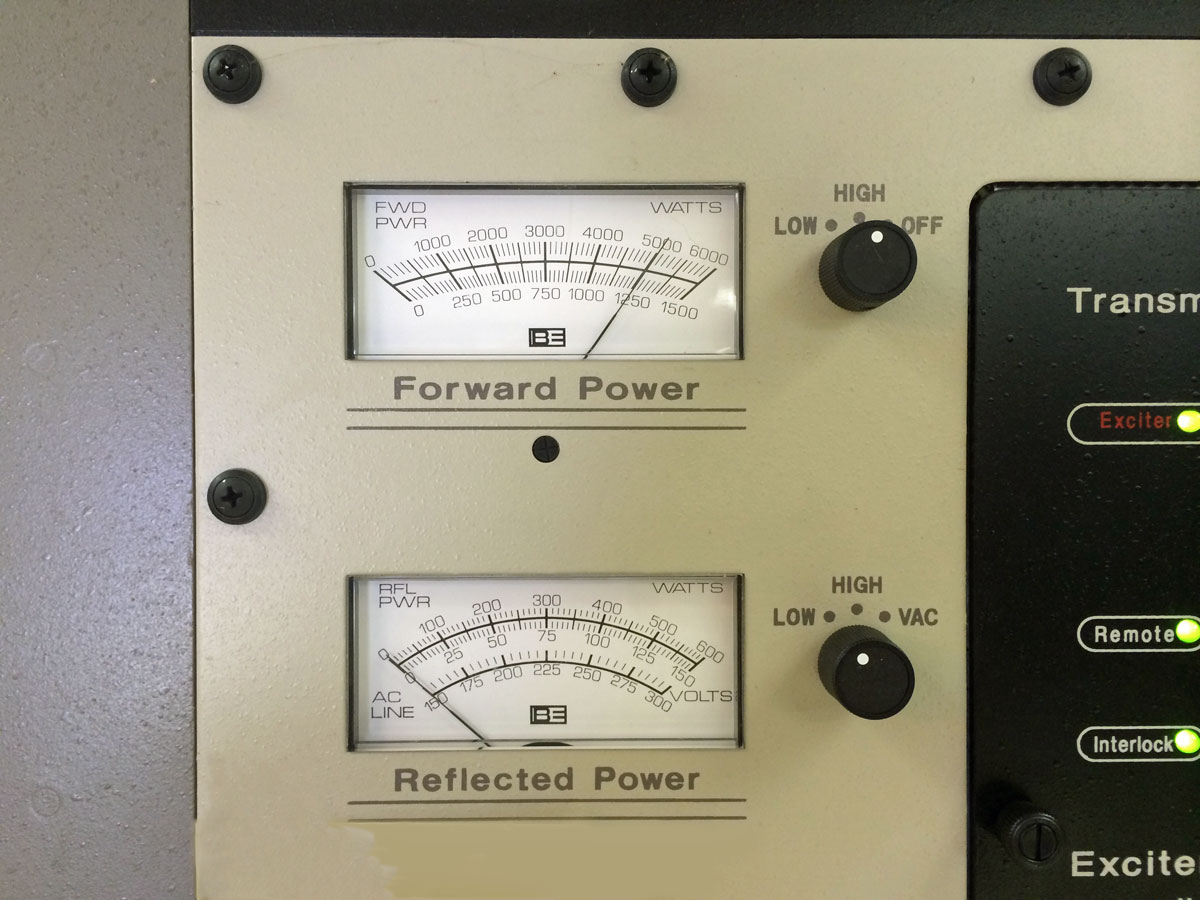
This was connected to a 202° tower. There were several complaints about seasonal shifts and narrow bandwidth. The VSWR meter would deflect slightly on high-frequency audio peaks, always a bad sign. A little bit of backstory is in order. WFAS signed on in 1930 using a four-legged self-supporting tower. This tower was used until about 1986, when it was replaced with a series excited, guyed tower. The ATU in use was initially designed for the replacement tower, which likely had a good bit of capacitive reactance. I am speculating on that, as I cannot find the original paperwork for the replacement tower project. At some point, somebody decided to ground the tower and put a skirt on it, likely to facilitate tower leasing. The skirt was installed, but the ATU was never properly reconfigured for the high inductive reactance from the skirted tower. The truth is, the Collins 820-D2 or Gates BC-1G tube-type transmitters probably didn’t care. They were probably like; bad load, meh, WHATEVER! Although the audio quality likely suffered. That all changed when Broadcast Electronics AM1A was installed. To fix the bad load problem, a BE 1 KW tuning unit was installed next to the transmitter.
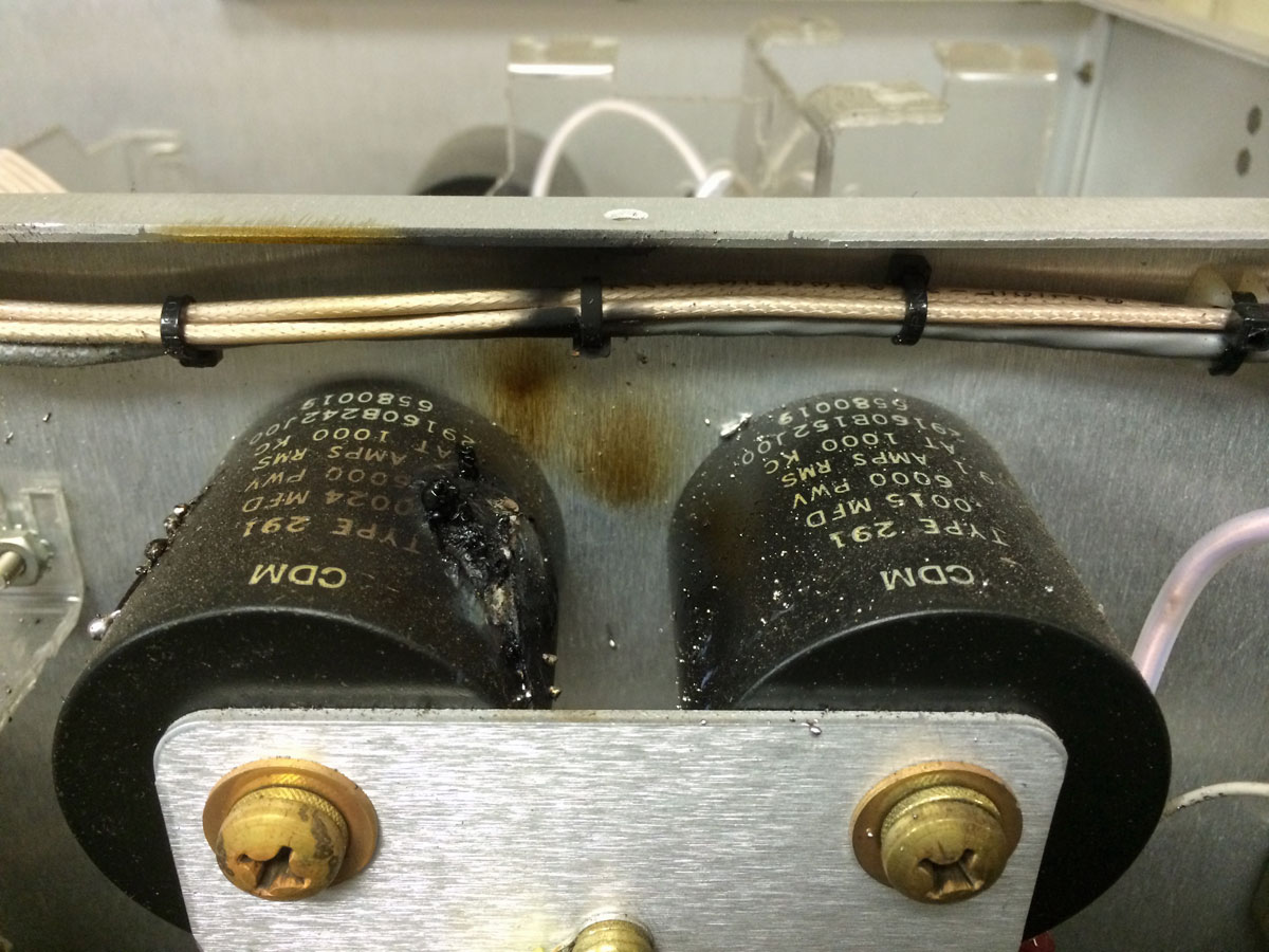
Technically, there are several problems with the above circuit, starting with the capacitor on the wrong side of the base current meter. This capacitor was installed outside of the ATU between the tower and ATU output. Was the base current meter really measuring the base current? I don’t know, maybe? The shunt leg was lifted but both of the inductors of the former T network were left in the circuit.
We reconnected the shunt leg and moved the capacitor inside the ATU and to the correct side of the base current meter. After several hours of tuning and fooling around with it, the ATU is still narrow-banded, although now at least the input is 50Ω j0. I believe the current design has too much series inductance to be effective.
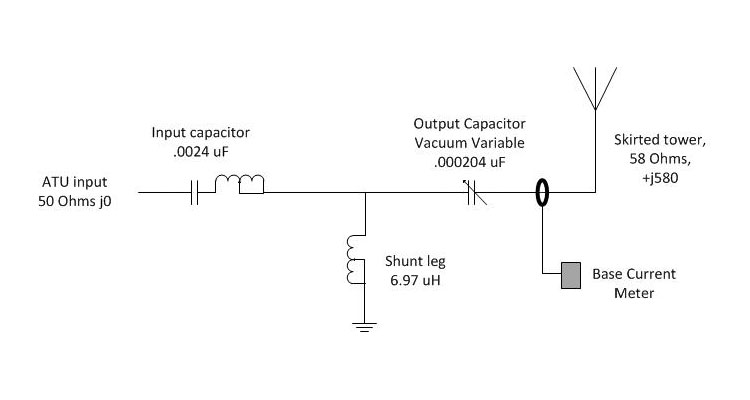
Thus, a redesign is needed. I think, because of the inductive reactance of a skirted tower, a phase advance T network will lead to best bandwidth performance. The basic design for a +90-degree phase advance looks like this:
To calculate the component values for the ATU, some basic arithmetic is required. The impedance value for each leg in a +/- 90 degree T network can be calculated with the following formula:
Z = √(inputZ × outputZ)
Where Z = impedance per leg
Input Z = the ATU input impedance, 50Ω
Output Z = the antenna resistance, 58Ω
Thus: Z =√ (50Ω × 58Ω)
Z = 53.85Ω
Formula for Capacitance: C = 1/(2Π × freq × XC)
Thus for the input leg: C = 1/(6.28 × 1.23MHz × 53.85Ω)
C (input) = 0.0024 μF
Formula for Inductance: L = XL/(2Π × freq)
Thus for the shut leg: L = 53.85Ω /(6.28 × 1.23 MHz)
L (shunt) = 6.97 μH
For the output leg, we must also consider the inductive reactance from the tower which needs to be cancelled out with capacitance. Thus, the output capacitor needs to have a value of 53.85Ω + 580Ω = 633.85Ω
Thus for the output leg: C = 1/(6.28 × 1.23MHz × 633.85Ω)
C (output) = 0.000204 μF
The amazing thing is, all of these components are available in the current ATU, they just needed to be rearranged. The exception is the vacuum variable capacitor, which I salvaged from an MW-5 transmitter many years ago. I donated that to the project, as I am tired of looking at it in my basement. The reason for the vacuum variable capacitor will become evident in a moment. The input capacitor will be slightly over value, which will require the inductor to tune out the excess capacitance. A good design rule is to use minimum inductance to adjust the value of a fixed capacitor, thus the capacitor should be not more than 130% of the required value.
About the Vacuum variable output capacitor; in the existing ATU had a 0.0002 μF capacitor already. With a +90° phase shift, this capacitor is likely adequate for the job. The vacuum variable may be pressed into service if something other than a +90° phase shift is needed for optimum bandwidth. That will be the topic of my next post.
Final consideration is the current and voltage ratings of the component. As this is a re-build using existing components, chances are that they already meet the requirements. On a new build or for replacing parts, one must consider the carrier power and modulation as well as any asymmetrical component to the modulation index. For current and voltage each, the value is multiplied by 1.25 and then added to itself. For a 1,000 watt carrier the input voltage on a 50 ohm line will be approximately 525 volts at 10 amps with 125% modulation. A good design calls for a safety factor of two, thus the minimum rating for component in this ATU should be 1050 volts at 20 amps, rounded up to the next standard rating. The capacitor on the output leg should be extra beefy to handle any lightning related surges.
The current rating for a capacitor is usually specified at 1 MHz. To convert to the carrier frequency, the rating needs to be adjusted using the following equation:
IO = IR√ FO
Where:
IO: current rating on the operating frequency
IR: current rating at 1 MHz (given)
FO: operating frequency in MHz
The vacuum variable output capacitor is rated for 15,000 volts, 42 amps. Adjusted for frequency, that changes to 46 amps. The calculated base current is 4.18 amps carrier, 9.41 amps peak modulation. Thus, the capacitor on hand is more than adequate for the application.