Class Charlie fire in the transmitter room electrical panel. Away fire party from repair locker forward. Set condition ZEBRA throughout the ship, this is not a drill.
Or something like that. If you were driving around Albany, NY this afternoon and noticed WDCD-FM was off the air, this is the reason why.
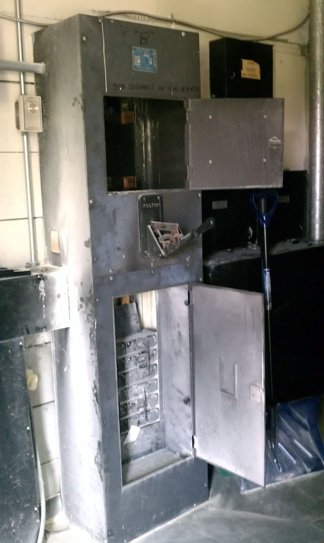
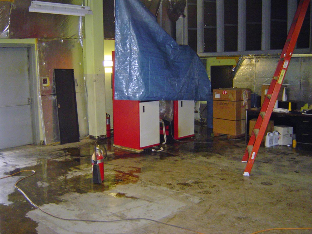
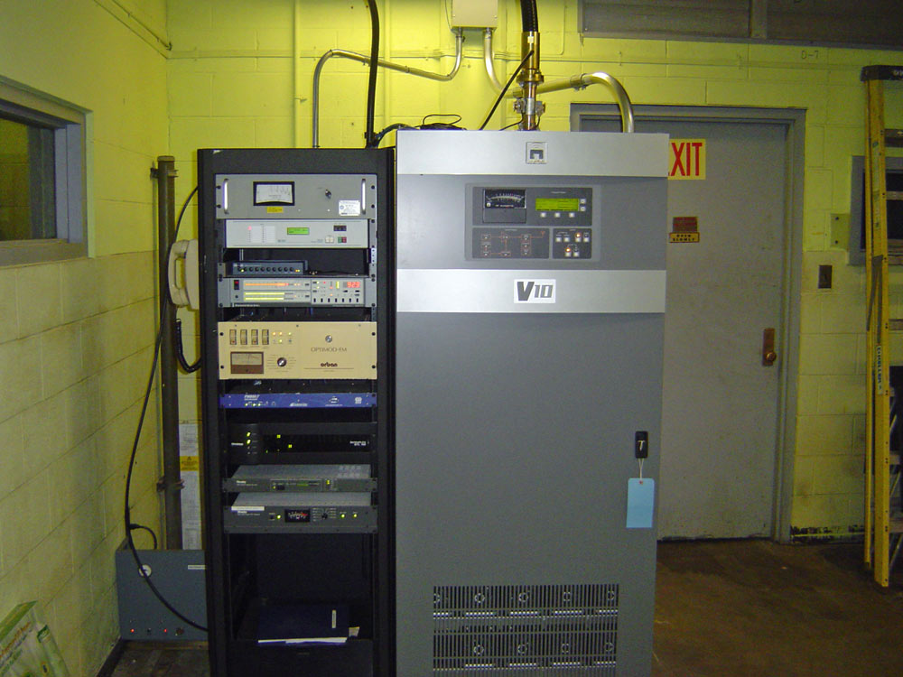
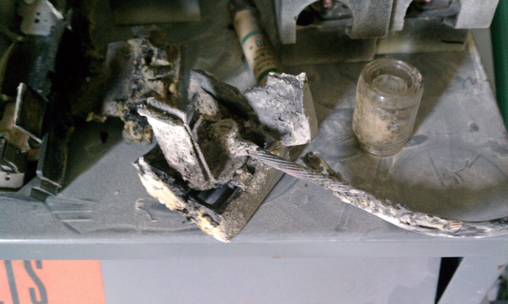
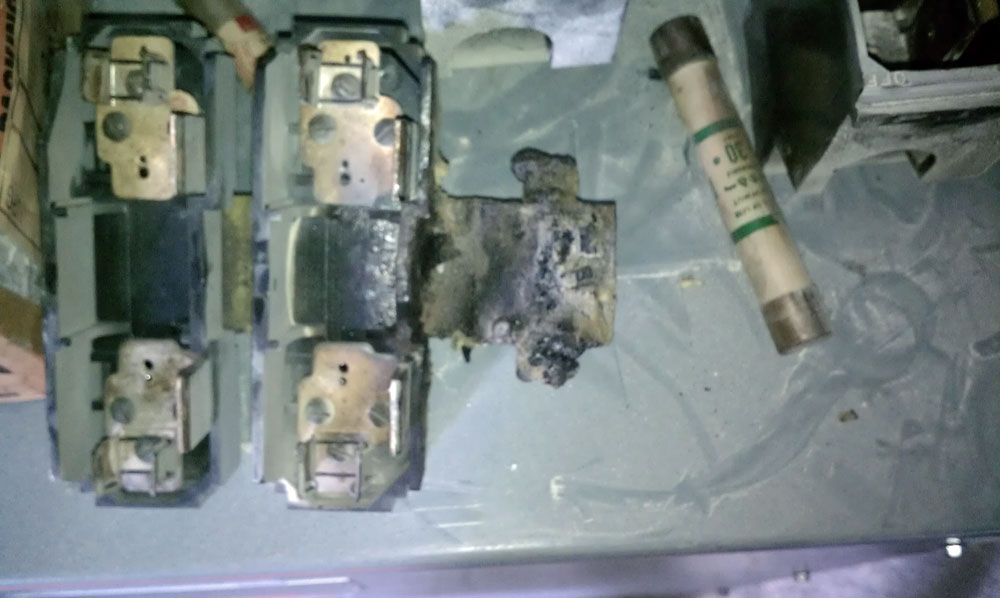
A little after noon time, the 480-volt main distribution panel at WDCD AM/FM caught fire, taking the FM station off the air.
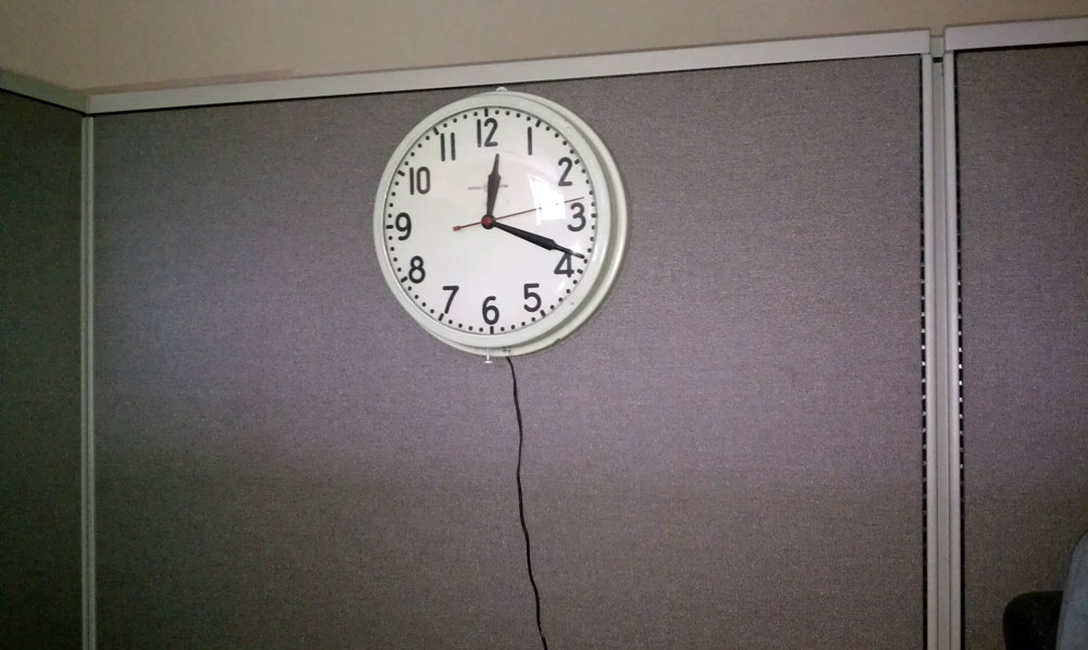
According to this clock, it happened at 12:19 pm, when there was a loud bang and the lights in the studio flickered several times, followed by the building fire alarm going off. Thankfully, a quick response by the station staff and the Town of Colonie fire department limited the damage to the interior of the distribution panel. Other than the dry chemical fire extinguisher residue all over the place, the building is none the worse for wear.
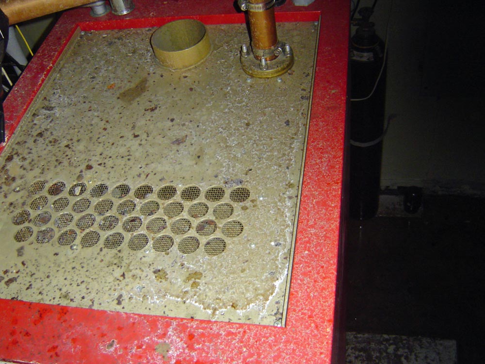
The 480 Volt three-phase electrical distribution panel was installed in 1947 when the original building was constructed. The power company cut the power to the building and an electrician was able to re-route the distribution for the dry step-down transformers that power the studios and equipment racks. The original 480 volt service was installed due to the 50 KW AM transmitter for WPTR (WDCD-AM). Currently, WDCD-AM is silent, pending programming decisions by the owner, Crawford Broadcasting.
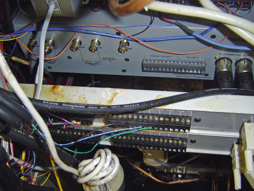
So, we spent the late afternoon vacuuming the NextGen computers and UPS out, wiping down the equipment, and making sure to clean out the power supplies and other nooks and crannies. Then, we powered everything back up, one at a time, and to our pleasant surprise, all came back up without error. The total off-air time for the FM station was about 6 hours.