Cell carriers generally do not like working on AM towers. It is out of their comfort zone and adds a layer of complexity to the project. However, sometimes they don’t have a choice, mainly when there is an existing site and they need to make changes. We have also had mixed results with tower contractors employed by various cell carriers. In one incident, a contractor showed up and re-tensioned the guy wires breaking all of the porcelain insulators. Another time, a contractor showed up to install footings 10 feet away from the tower and ripped up all the ground wires. One tower climber found one of the skirt wires was in his way, so he cut it off with a hack saw.
Those experiences demonstrate that it is far less expensive to have somebody on site while tower contractors are doing installation work on any skirted AM tower. And so it was today.
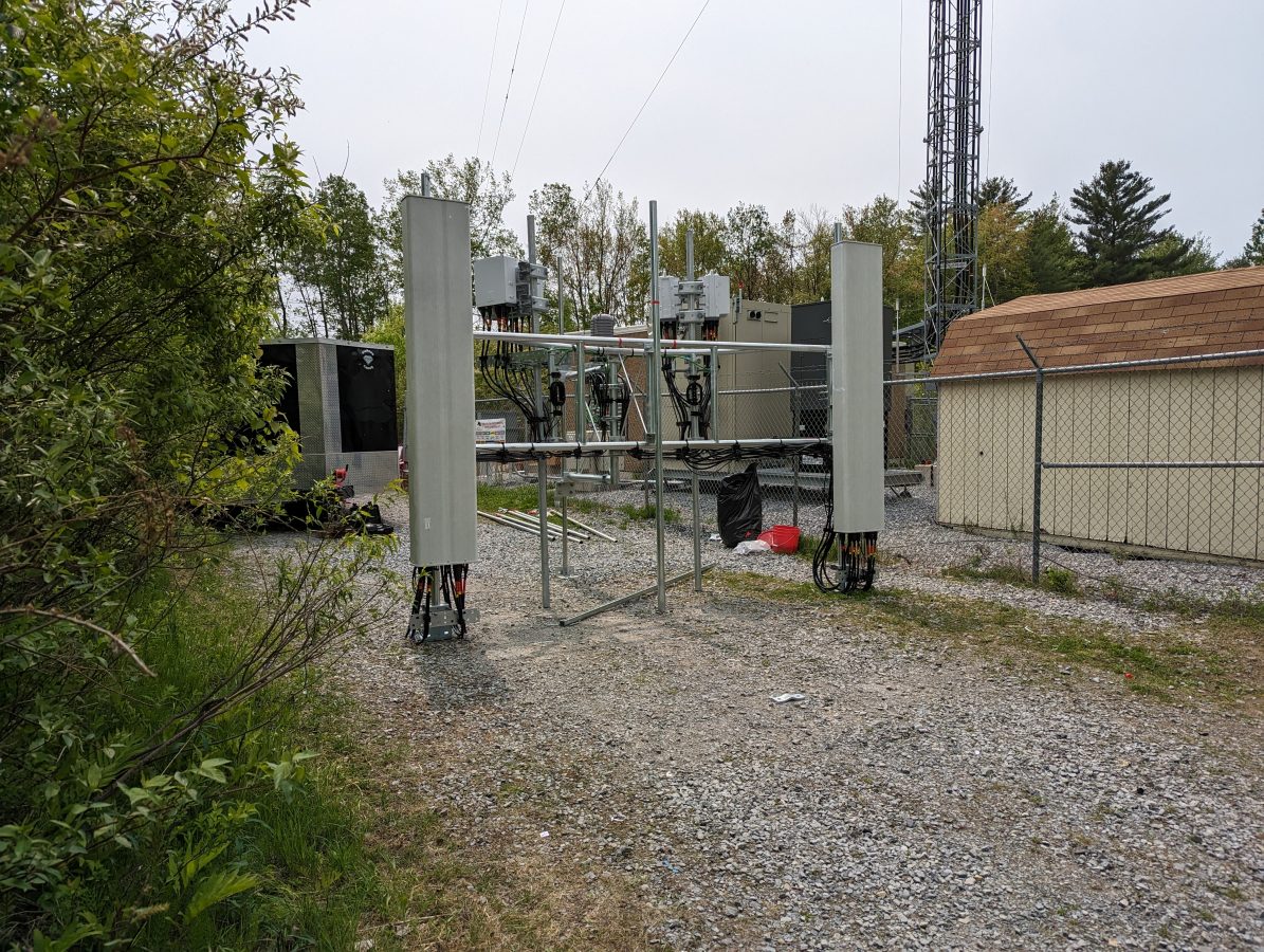
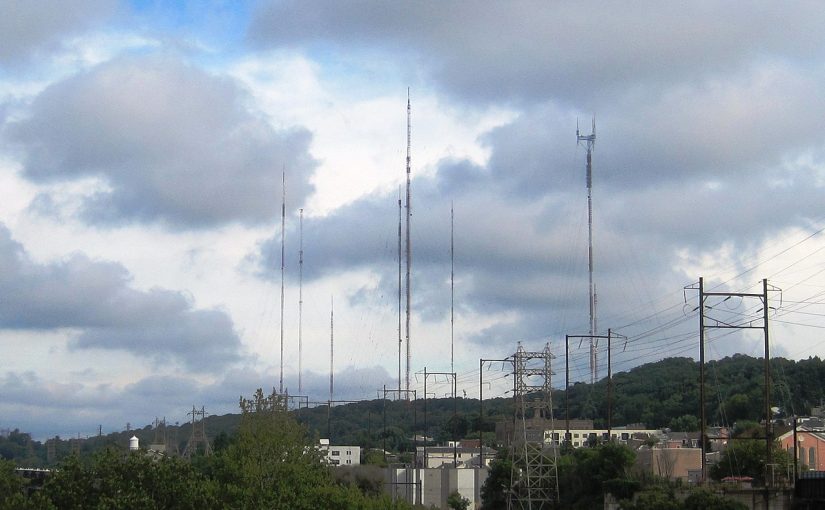
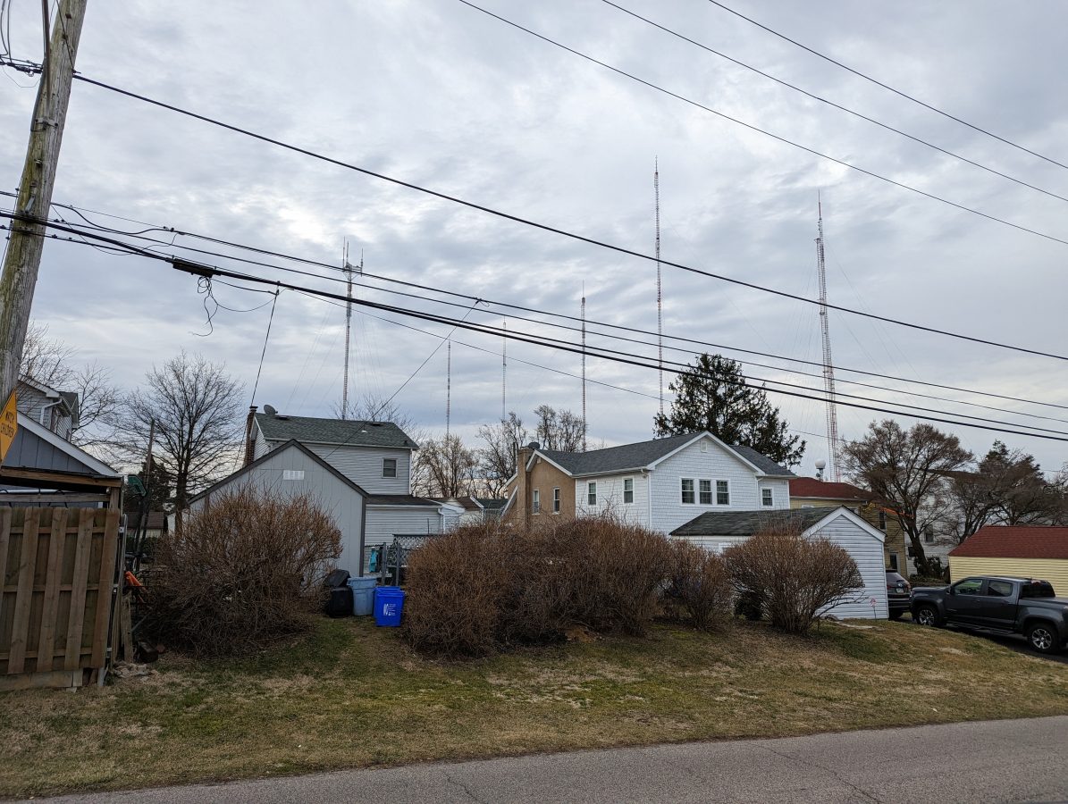
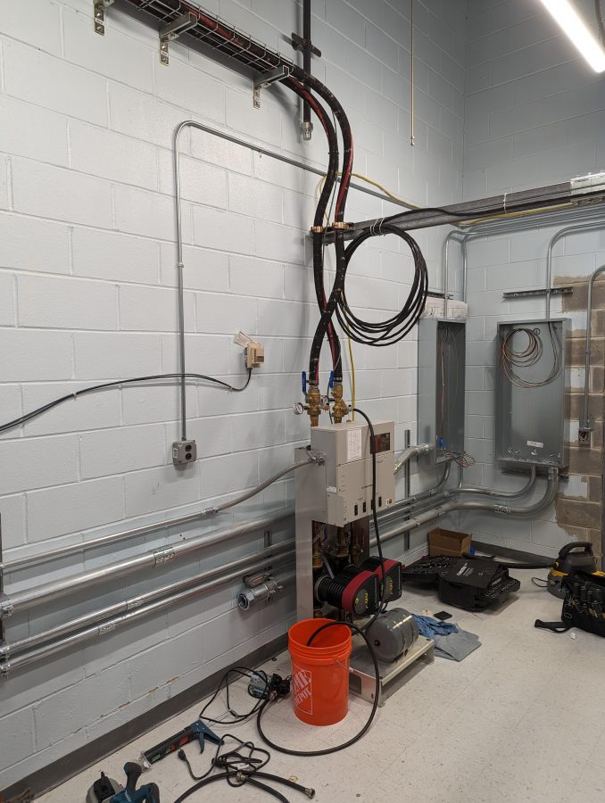
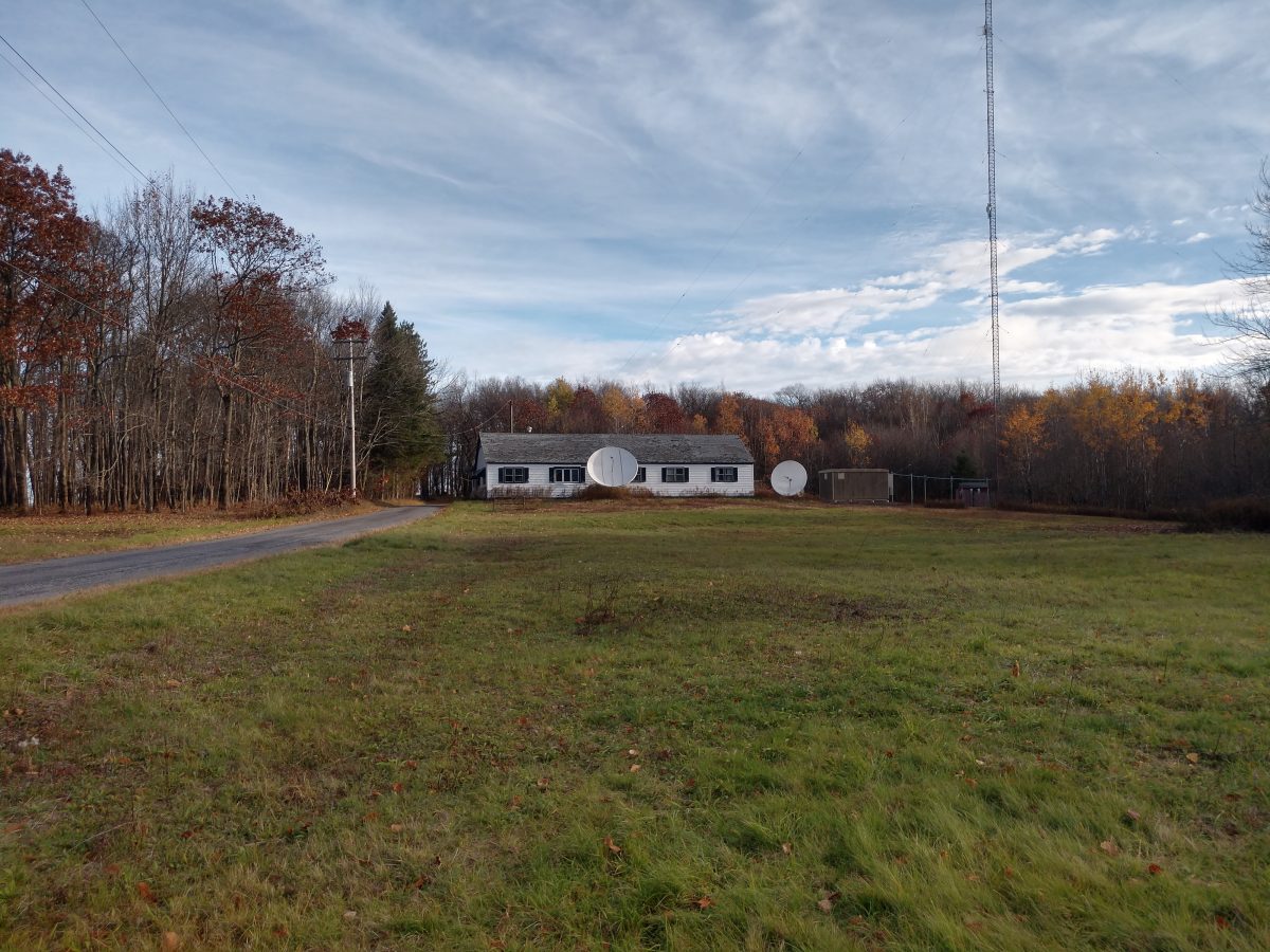
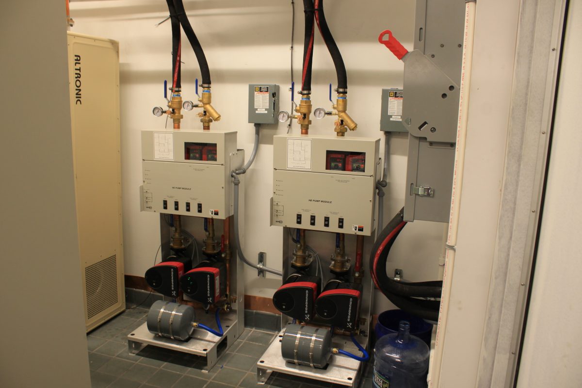
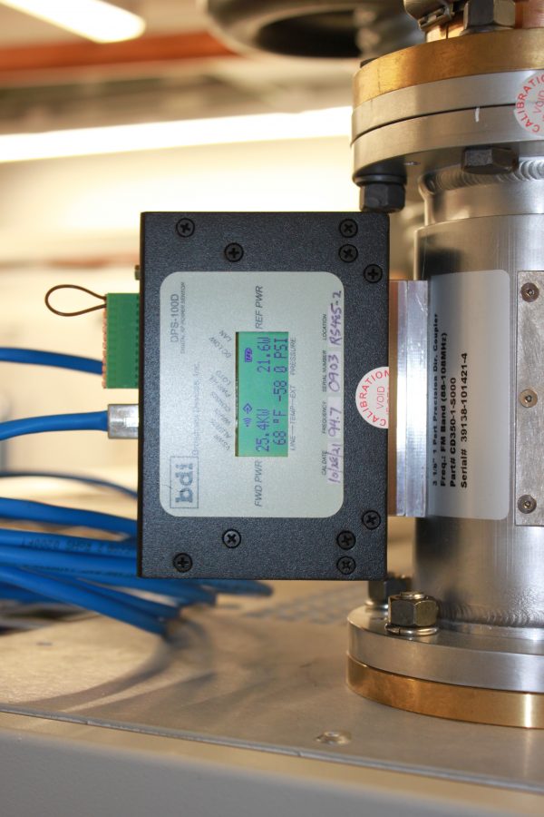
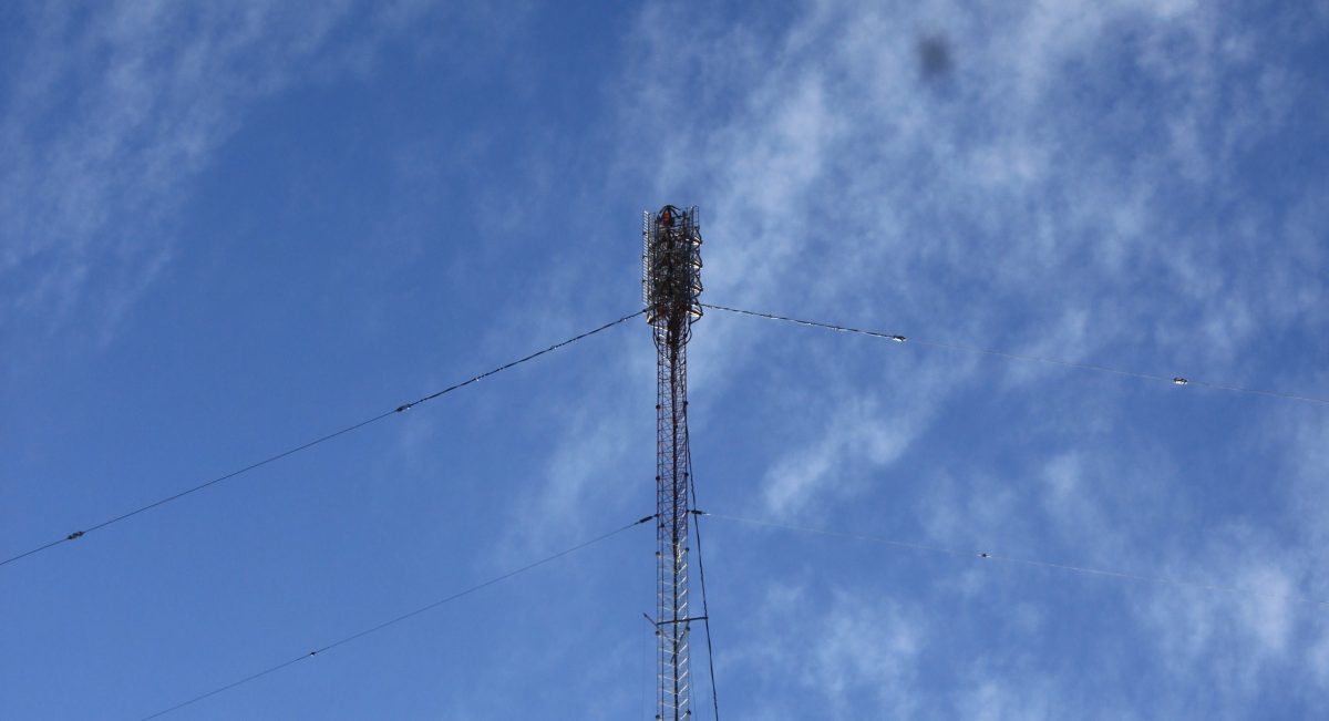
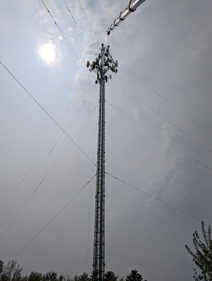
This tower has two AM stations diplexed as well as two FM translators combined into one Nicomm antenna. We did before measurements on the AM stations using an OIB-3. Once the installation is done, we will do the after-measurements and then assist the licensee with any FCC 302 filings if the base impedance has changed significantly.
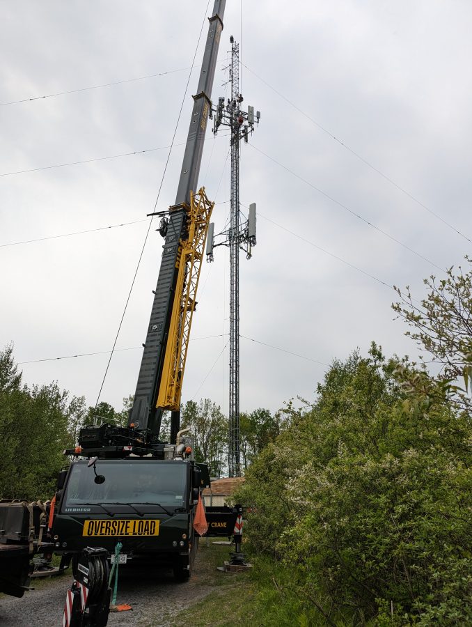
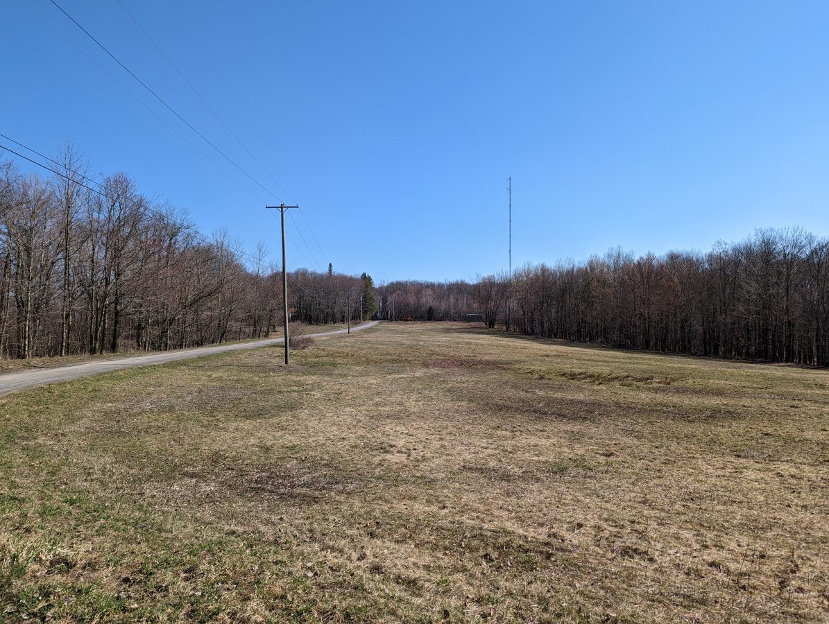
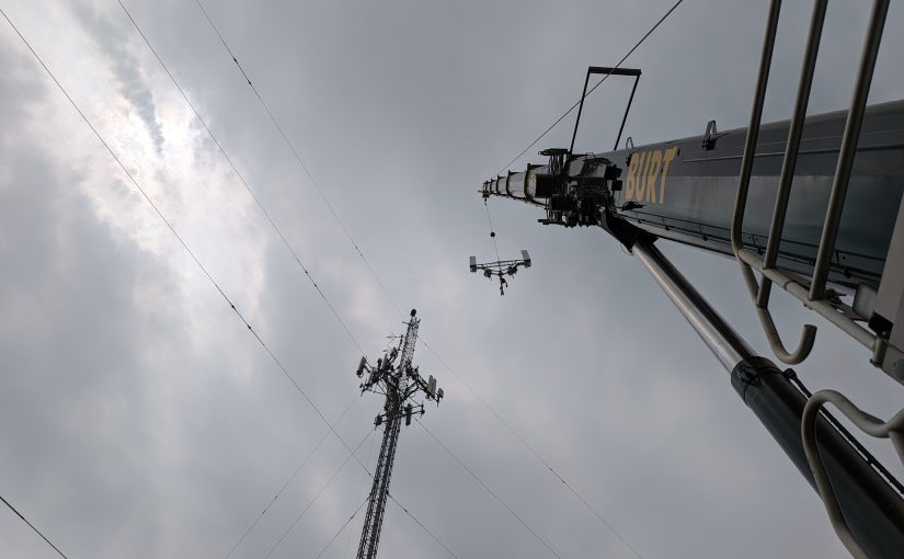
With each lift, I went out to the base of the tower and made sure that the skirt wires were clear of the mounting brackets and not touching anything else. The tower crew was Russian speakers. When they asked if the transmitter was still on, which was kind of comical (he motioned to the skirt wire, made like he was grabbing it, then jerked around like he was being electrocuted). I had to wrack my brain to try and remember: Передатчик выключен. The literal translation is “Not working.” The difference between “working” and “not working” is one consonant at the beginning of the second word which is pronounced soft for off and hard for on.
This site was the subject of a previous post: A tale of five signals.