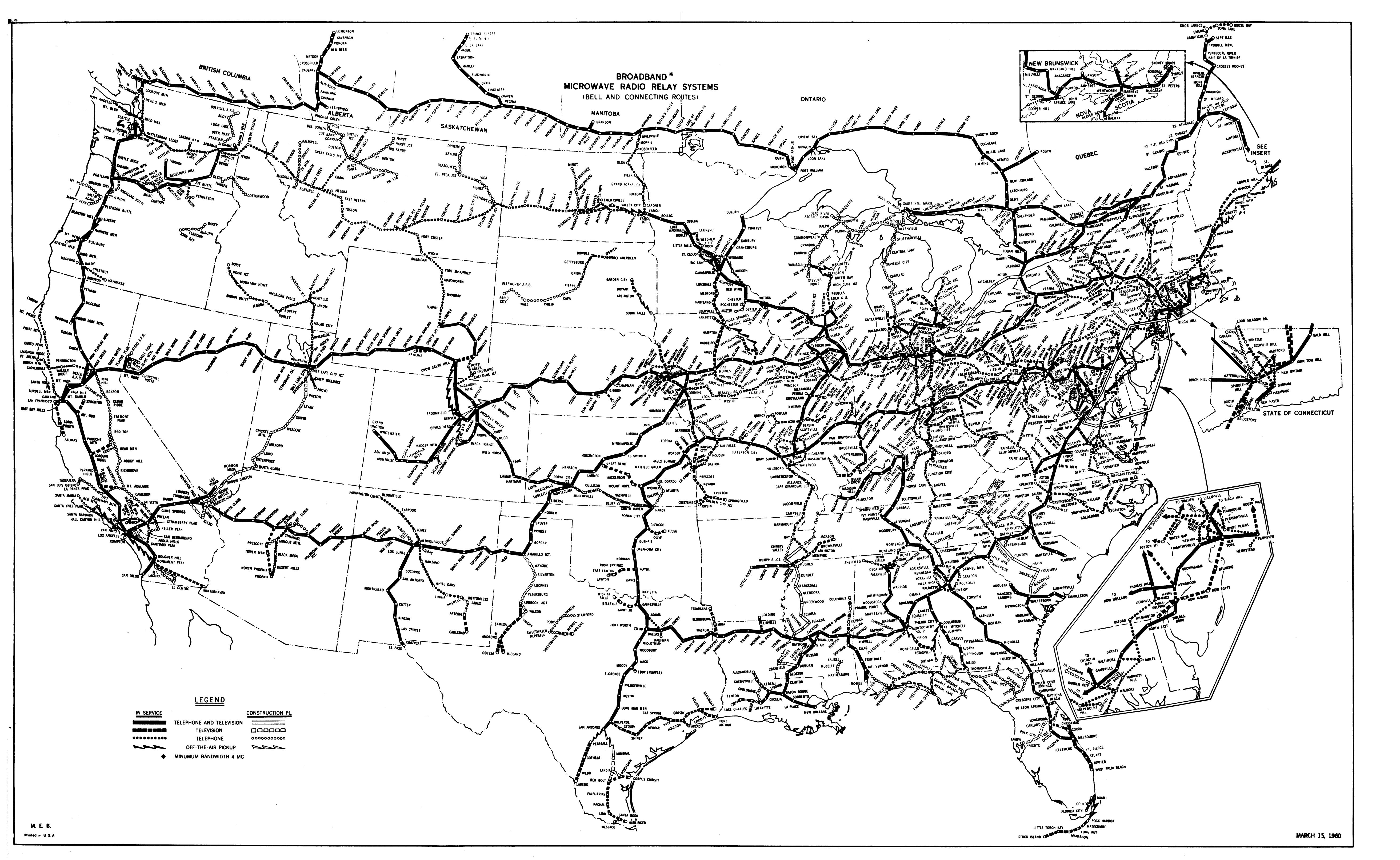
Milwaukee’s oldest radio station

WISN 1130 AM has been on the air since 1922, although not always with those call letters.  In an interesting twist, the license was granted to the local newspaper, the Wisconsin News, and the Milwaukee School of Engineering.  Initially, both entities were programming the station, however, by about 1925, the newspaper was responsible for programming and the engineering school was responsible for technical operations.

In 1941, the station increased power from 1,000 watts to 5,000 watts and added nighttime service.  This is a series of pictures from that time period.

WISN night time allocation study

Back in 1941, nighttime interference was taken seriously.  The nighttime allocation study (on 1150 KHz, WISN’s former frequency) includes co-channel stations in the US, Canada, Cuba, and Mexico.

WISN night time allocation ma

The array consisted of four Blaw-Knox self-supporting towers in a rectangle.  Notice the lack of fencing, warning signs, and the like around the towers.

WISN antenna array
WISN antenna array

From the front of the transmitter building

WISN transmitter site, 1941

The site looks well designed, no doubt manned during operation, which at the time would likely be 6 am to midnight except under special circumstances.   Most of these old transmitter sites had full kitchens, bathrooms, and occasionally a bunk room.  The transmitter operators where required to have 1st telephone licenses from the FCC.   There is only one manned transmitter site in the US that I know about; Mount Mansfield, VT.  There, WCAX, WPTZ, WETK, and VPR have their transmitters.

WISN RCA BT-5E transmitter, 1941

The WISN RCA BT5E transmitter looks huge for that power level.  Back in the day when AM was king, these units were designed to stay on the air, no matter what.  I don’t know too much about this model transmitter, but if it is like other RCA/GE models from the same era, it has redundant everything.

RCA AM antenna monitor

Old school antenna monitor.  I have never seen one of these in operation, however, as I understand it, the scope was used to compare the phase relationship of each tower against the reference tower.

These pictures are of the WISN 1150 array was it was in 1941.  Since then, the station has changed frequencies to 1130 KHz and increased power to 50,000 watts daytime/10,000 watts night time.  The daytime array consists of six towers and the night time array has nine towers, all of which are 90 degrees.

Special thanks to John A. for sending these pictures along.

The Tandy TRS-80 Model 4D computer

File under: You can find the darnest things at the transmitter site. Near as I can tell, this computer dates from about 1985 or so, it looks remarkably like my Apple IIe of the same vintage.  We used an earlier model TRS-80 in high school, that model had a cassette deck as the data storage device.  These have 5 1/4 inch floppy disks.  I used my Apple IIe as a gloried type writer, mostly for college papers.  I did manage to write some basic programs, no doubt copied from somewhere else.

For the day though, saving something for later editing, even to a floppy drive, was an order of magnitude over the single spaced type written page.

Tandy TRS-80 Model 4D computer

There are actually two of these computers, serial numbers 7086 and 7128.  I have no idea whether they work.   I’d donate them to a museum if there were one that was interested.  Otherwise, they may sit in the corner for another twenty years or so.

WICC Station Operating Report

From February 8, 1940:

WICC operating report, February 8, 1940

I found this in one of the file cabinets at the transmitter site.  It was apparently used as scrap paper because there is what looks like connection information for a remote control system scrawled on the back.  I thought it was interesting as it shows a 6 a.m. sign-on and the type of programming, source, and exact times each element ran.  For Origins, YN = Yankee Network, BPT = Local Studio (Bridgeport), and NBC = NBC.  Program logs for later years (1943) show the Alarm Clock Salute was received via FM from W43B (Paxon, MA) on 49.3 MHz.

Sign-off was at midnight.  It must have been cold in that little house out on the island in February.

Anyway, I’ll save these in my radio station history files.

The 100 amp fuse

I found this fuse in an old electrical panel that we were removing from the WICC generator shed.  This was the original service entrance for the site as it was built in 1932 or so.  The generator shed had a manual three pole two position transfer switch, which was fine back when a licensed transmitter engineer was on site whenever the station was on the air.  The generator, according to the old records I could find, was an upright 2-cylinder slow-speed engine with a belt-driven generator.  They were mounted on concrete pads about 5 feet apart.  The motor had a big flywheel that was hand-cranked with the compression off.  Once a good head of speed was built up with the hand crank, the compression lever was thrown and the engine would start.  Alternatively, the procedure was tried again.

That was all replaced in 1971 when the transmitter site underwent a major upgrade.  The old electrical service was bypassed and abandoned in place when a new meter and panel were installed in the transmitter building.  The old service seems to have been frozen in time, untouched for forty years.

Kirkman Engineering renewable fuse

This fuse is a Kirkman Engineering Company and has a manufacture date stamp of January 1945.  It is a replaceable link AKA “renewable” fuse.  It has “peak lag” links, which I think would be called “slow blow” today.  Peak lag may also indicate a large inductive load, which would lower the power factor.  What I find interesting is that someone, once upon a time, placed two 100 amp links in parallel, then crossed the 100 AMP label out and wrote “200” on the fuse body.

Kirkman Engineering fuse links

The problem with this setup is that the panel and wiring were all rated for 100 amps.  The wiring is #4 copper, and the transfer panel and switch are clearly labeled “100 amp, 3 pole.”  It would appear that the finger stock holding the upper blade in place was loose, causing the fuse body to overheat.  In fact, it became so heated that the case and the wood fiber holder were charred and missing.

Fortunately, there was never a fire.

The reason why we use properly sized fuses and breakers.