Mixed, at least in my neck of the woods. I was stationed at an LP-1 station which was monitoring a PEP station directly. On my end, the test went fine without intervention. Please excuse the cellphone video, I am used to my good camera, which I left at home.
Many others in the New York area had problems. Stations with newer SAGE (Blue front) CAP-capable EAS ENDECS had issues, even the ones that were also monitoring the PEP stations directly.
Many of those stations broadcast the header tones and about 10 seconds of audio. The audio abruptly stops and is followed by twenty seconds of dead air followed by the EOM. I can speculate that the SAGE EAS units should be checked for proper configuration and be tested back to back while receiving duplicate messages from different sources spaced apart by ten seconds.
Several stations downstream from the LP-1 stations did not receive anything at all. Others received the alert tones but no audio, some had high levels of background noise, thirty seconds of static, audio cut off, etc. All in all, most would look at this and say “Thank God it wasn’t a real emergency.” Silver lining: For all those that are concerned that the federal government will attempt to diabolically take over the entire broadcast spectrum and say evil things; Doh! foiled again.
It is a pretty good simulation of what will happen on November 9th. The script used is not the actual script that will be used for the national test.
After the test, the video shows how to bail out of the national test in the event that a valid EAN is not received. This is important information, as this particular failure has occurred many times in the past. If the LP-1 or PEP station that transmitted the test fails to send a valid EOM, the EAS unit will continue to transmit that station’s programming indefinitely. If the LP-1 or PEP station resumes regular programming while the EAS unit is relaying their programming over the air, that would be a good indication that the LP-1 or PEP station has failed to send a valid EOM.
Since the FCC waved some of its rules regarding carrier power and carrier shift on the AM broadcast band, AM stations are now able to implement MCDL or DCC (Dynamic Carrier Control) technology to save money on their electric bills. This technology has the potential to save tens of thousands of dollars for higher-powered AM stations (high power=greater than 10 KW carrier level).
On a standard AM broadcasting station, the carrier represents two-thirds of the energy being transmitted, with the modulation index containing the other one-third. The carrier contains no information; it is simply there on the center frequency at the power level authorized by the station’s license. Thus, if the carrier can be reduced without affecting the quality of the broadcast reception, it will reduce to the overall power consumption of the transmitter. In areas where electric costs are high, the savings can be substantial.
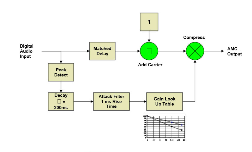
There are various ways to accomplish this. The first is called Dynamic Carrier Control (DCC), where the carrier voltage is reduced during moderate modulation levels (between 20-50%) and restored during peaks. This reduces the output power during average modulation, restoring most of it during quiet periods and peaks. The next is Dynamic Amplitude Modulation (DAM), which is similar to DCC. The most savings will be noted with less heavily processed programming such as talk radio because the higher the average modulation density is, the less the MDCL circuit reduces the carrier voltage level. The little graph in the diagram shows the reduction in the carrier voltage vs. modulation levels.
Nautel DAM block diagram, courtesy of Nautel, Ltd.
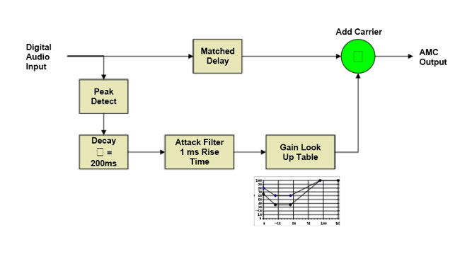
Finally, Amplitude Modulation Companding (AMC) reduces the voltage in both the carrier and modulation product during peaks. This results in better savings for higher-density modulation indexes. It is also the most transparent of the three schemes, as the carrier is restored to full power during periods of low or no modulation levels. During peak modulation, the reduction does not drop the power level below the un-modulated carrier level. The little graph in the diagram shows the reduction in the carrier voltage vs. modulation levels.
Nautel AMC block diagram, courtesy of Nautel, Ltd
Nautel has done extensive work on MDCL and includes several algorithms in their NX series transmitters. For older Nautel transmitter models such as ND, XL, XR, and the J-1000, there is an outboard exciter, which is in a one-rack unit chassis. Older transmitters may need a simple field modification to create a DC-coupled audio input. The cost for the upgrade is approximately $5,000 USD, however, check with the regional Nautel sales rep.
Once the system has been installed, there are several things to be aware of:
Modulation monitors may not work properly, especially older units, which will show significant carrier shifts and have carrier alarms. Belar AMMA-2 modulation monitor is specifically built to work with MDCL transmitters.
When making field strength readings, the MDCL circuitry must be turned off to get accurate readings.
For stations running IBOC, the amount of carrier power reduction may need to be experimented with, as the effect of the carrier reduction may cause the transmitter to exceed the NRSC mask.
Currently, only Nautel and Harris are selling MDCL transmitters. I spent several minutes poking around the Harris website and looking through their product brochures for the DX series transmitters and no mention of DCC o MDCL was found. I’d be happy to include any information from Harris if it were made available.
Somehow I missed this one when it first circulated last July. I think I was out on the lake fishing or something. I suppose a bunch of lawyers would not know the difference between a correctly wired antenna and an incorrectly wired one.
Another one:
Department of Jammed Gears
If only these were some sort of clever fake, a spoof, or something like that. But no, this is the real deal. The Department of Innovation’s best work is a logo of jammed gears. I wonder how much that cost.