The Nautel XR6 AM transmitter

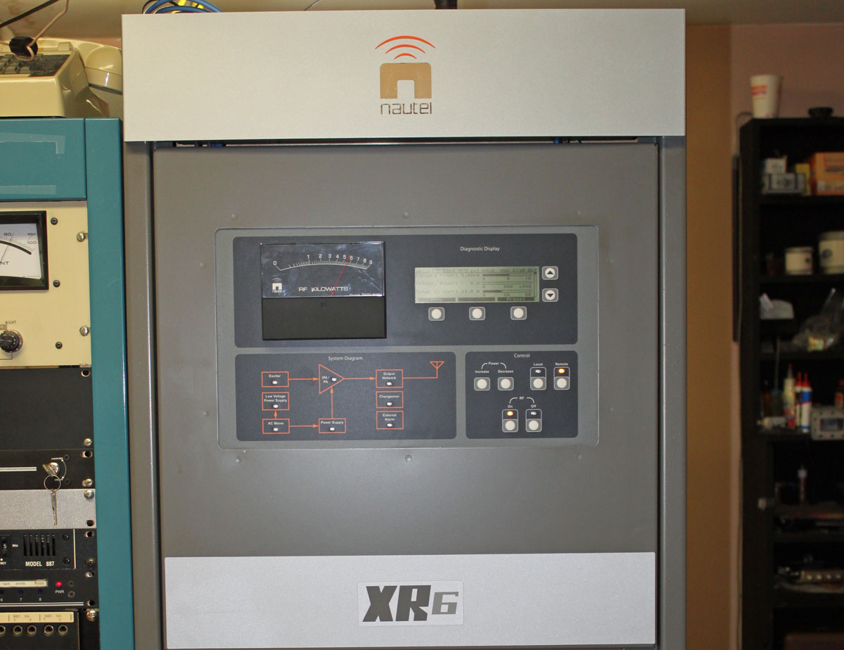
I’ve been away working in Burlington, VT (WVMT, 620 KHz, Burlington)  for the last coupla, installing this nifty Nautel transmitter:

Nautel XL6 transmitter, WVMT Burlington, VT
Nautel XR6 transmitter, WVMT Burlington, VT

I like the Nautel units, both AM and FM;  they are well-designed, well-built, rugged transmitters.  I have lost track of how many of these units we service in the field, partly because they are becoming pretty much standard equipment at all of our installations.

Continental 315R-1 AM transmitter, WVMT, Burlington, VT

The transmitter it is replacing is a Continental 315R-1, which is based on the Collins Power Rock design.  It is a PWM transmitter with a 15,000 volt power supply.  In their day, these were not terrible transmitters, however, like their Harris MW-5/10/50 PDM brethren, frequent thorough cleaning is required to keep the dirt/dust from arcing over.  Unfortunately, it is becoming more and more difficult to obtain parts for these units. This transmitter was installed in October of 1983, thus, almost thirty years of service is quite enough.  This unit we did not cut up and scrap, rather, it is sitting by the back door, waiting for any takers.

Continental 315R1 modulator/RF sections
Continental 315R-1 modulator/RF sections

The interior of the Continental 315-R1 transmitter.  Modulator section is on the left, RF section is on the right.

The good news is, WVMT is another one of those “successful AM station” stories.  You know, the kind of station that has local programming, local sports, news, community presence and most importantly, makes money.  For all those diligently studying the “AM Problem” for the up and coming NAB conference this April, here is a clue: It’s the programming…

Nautel XR6 transmitter, wvmt Burlington, VT
Nautel XR6 transmitter, WVMT Burlington, VT

This is the Nautel XR-6 on the air.  Positive peaks, anyone?

AM modulation monitor

We turned that down a little bit.  Also, the station does not run AM stereo, the AM stereo mod monitor is simply a usable relic of a bygone era.

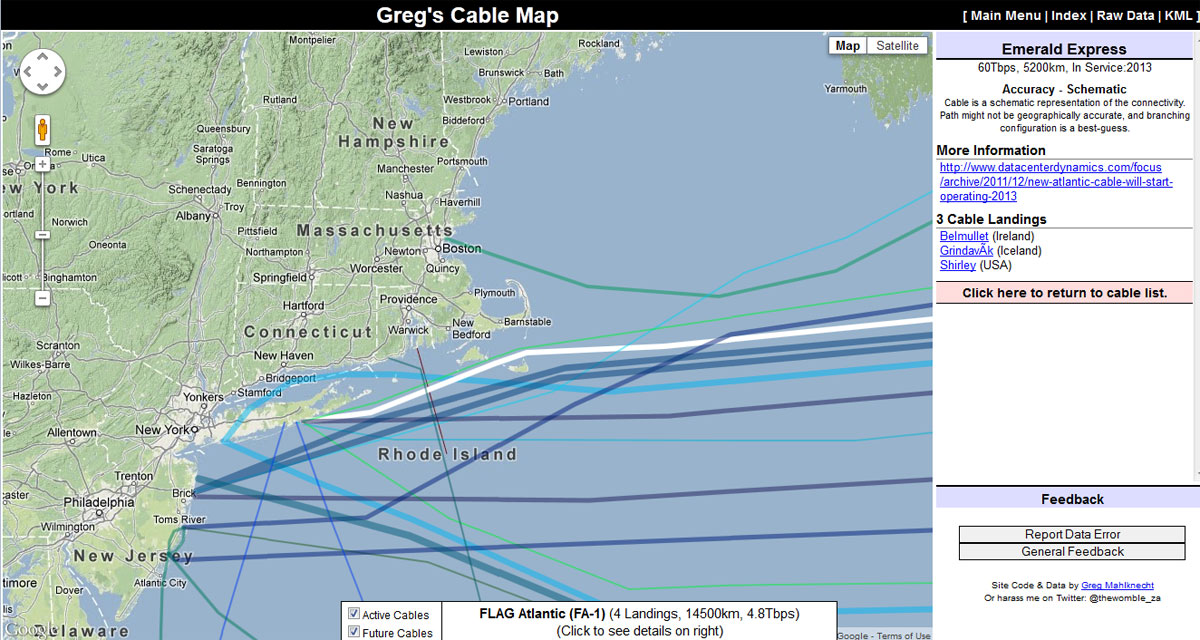
WVMT is noted as the first radio station licensed to the state of Vermont, signing on on May 10, 1922.  It has a three tower directional array located down in the swamp.  For some idea of perspective, it is 1,150 feet (350 meters) from the transmitter building to the center tower, the towers are 411 feet (125 meters) tall spaced 405 feet (123 meters) apart.

WVMT three tower directional antenna array, Burlington, VT
WVMT three-tower directional antenna array, Burlington, VT

WVMT antenna system from back of transmitter/studio building.  That is a long walk over rough terrain in the middle of the night or anytime really, but especially in the middle of the night.

Undersea Cable Map

With the advent of fiber optic cables starting in the 1980s,  the majority (one estimate says 99%) of this country’s overseas communications are carried by undersea cables.  These are interesting system constructions, being first redundant and second, self-healing.  Glass fiber stands themselves are fairly fragile.  Bundling several together and then sinking them in the ocean can create mixed results.  Deep ocean bottoms are often very rugged, containing mountains, canyons, and fault lines.  Thus the submarine cables used have to be pretty rugged.

There is a common misconception that fiber optic cables do not need repeaters.  That is not true, while they do not need as many repeaters as copper cable, repeaters are still required approximately every 40-90 miles (70-150 km) depending on the cable type.  These active devices are another failure point.  Overall, it is a complex system.

Submarine Fiber Optic Cable cross section
Submarine Fiber Optic Cable cross-section, courtesy of Wikipedia

Cross-section of a submarine fiber optic communications cable:

1. Polyethylene
2. Mylar tape
3. Stranded metal (steel) wires
4. Aluminum water barrier
5. Polycarbonate
6. Copper or aluminum tube
7. Petroleum jelly
8. Optical fibers

It weighs about 7 pounds per foot, which is pretty hefty.

There are a couple of interactive maps online that have detailed information about where these cables go, date in service, and data capacity.  My favorite is Greg’s Cable Map which is a Google map with cable data overlayed with a downloadable KML file:

Undersea cable map
Undersea cable map

This shows a new cable called the “Emerald Express” which is going into service in 2013. Throughput is reported as 60 Tbps, which is moving right along.  As noted on the map, this is more of a schematic diagram connecting two shore side points.  The path the cable takes is an estimate and the actual geographical location may (is likely to) be different.  Click on any line on the map for cable information.  Most cables have their own web page and Wikipedia article.

Another undersea cable map is the Telegeography Submarine Cable Map, which has many of the same features noted above:

China US submarine Cable network diagram

Just in case you were wondering, as I often do, how a TCP/IP connection is being routed to any given place.  For fun, I tried a trace route to a known server on Guam and found the results interesting:

Trace Route, Guam
Trace Route, Guam

Approximately 231 ms round trip route from NYC to LA to Guam and back, which is over 8,000 miles (12,850 km). A few of the intermediate routers did not answer and I tried this several different times; the same routers time out.   This missing information looks to be small steps, not large ones.  So, which cable goes directly from LA to Guam?  Possibly the China-US Cable Network (CHUS) (picture above).  At 2.2 Tbps and landing at San Luis Obispo, that is the likely candidate for the cable that carried my data.

As a general exercise, it is kind of fun, although it may be harder to figure out a particular route to say London or Berlin because there are many more different possibilities.

Route latency is something to keep in mind when planing out AOIP connections for remotes and other interactive type connections between studio and remote location.  Almost nothing is worse than that half second delay when trying to take phone calls or banter back and forth with the traffic reporter.

h/t: jf

Restoration work on an RCA transmitter

I read through this article about the ongoing restoration work of an RCA SSB T-3 transmitter and found it interesting.  The RCA T-3 transmitter is a 20 KW SSB/ISB HF (2-28 MHz) unit designed for point-to-point telephony service.  Because SSB requires class A or AB low distortion amplifiers, this is a large unit, even for its age and power levels.

From the looks of the before pictures, this transmitter was in sorry shape.

Here is a brief video of the transmitter start-up:

These units were designed to be switched on and run at 100% duty cycle for most of their operating lives. That is some heavy iron there.  This particular unit was made in 1959. More here and video part 2:

Anyway, before geosynchronous satellites, HF point-to-point transmitters were used to make long-distance phone call connections and send data and pictures back and forth over long distances. Out in Hicksville, Long Island, Press Wireless ran a data and fax system that used HF for long-haul data transmission.  Much of the WWII reporting from Europe and the Pacific Theaters was carried over this system.

Text would be printed out on a mechanical teletype machine at something like 60 words per minute, which was considered fast for the time:

Tuning across the band, one can often hear Radio Teletype (RTTY or RATT) which uses a 5-bit Baudot code, 170 Hz shift with 2125 HZ representing a Mark or 1 bit and 2295 Hz representing a Space or 0 bit, which is a bit different from the Bell 103 modem specifications. This is what it sounds like at 75 Baud:

So slow you can almost copy that by hand.

The RCA H (SSB T-3) unit above was independent sideband (ISB), which means that either sideband or both could be modulated independently of the other, thus two channels of information could be transmitted.  SSB bandwidth is about 2.7 KHz, which is good for telephone-grade audio or low-speed data.

I sort of wish I was living in California again, I’d lend a hand.

Call Sign Trivia

I found this youtube video about Pittsburgh, Pennsylvania radio stations:

That’s cool and all that, but it brings up the question about the K/W calls which were misplaced during the early days of broadcasting.  Originally, call letters were assigned to ships and coastal radio stations in the following way:

Three-letter call signs were for coastal (land) stations.  K letter calls were for shore stations in the west and W letter calls were for shore stations east.  Ships were assigned four-letter calls, W calls signs were issued to ships homeported on the west coast and K calls for ships homeported on the east coast.  There was a period of time when a few K call letters were issued to east coast broadcasting stations, no one is quite sure why.  Prior to 1923, the K/W boundary was not the Mississippi River, but the eastern border of the states of Montana, Wyoming, Colorado, and New Mexico.  Thus, there are many more misplaced W call signs than K call signs.

Of course, KDKA and KQV come to mind. Philadelphia has KYW. What other misplaced call signs are there, e.g. W’s west of the Mississippi and K’s to the east?  Of course, one can google it and get an answer, however, there is one that is pretty obscure.