Somebody sent me a link to this video, I thought I’d share:
Author: Paul Thurst
The inglorious task of AM antenna array maintenance
AM radio stations are rough customers. They frequently operate on the margins, both in terms of ratings and revenue. Their transmitter plants are complex and very often have been on a reduced maintenance schedule for years, sometimes decades. Those of us that understand the operation of AM transmitter plants and all their quirky behaviors are getting older. I myself, feel less inclined to drop everything and run off to the AM transmitter site when things go awry. Seldom are such efforts rewarded, much less acknowledged. Station owners are also finding that their previous demands are unrealistic. For example, time was that any work that takes the station off the air had to be done after midnight. These days, I can tell you, I will not be working at your radio station after midnight. You can find somebody else to do that work.
Thus, today, we took this particular AM station off the air from Noon until 3 pm to diagnose and repair a problem with the four-tower daytime array. Once again, this involved a shift in common point impedance and a drastic change in one tower’s current ratios.
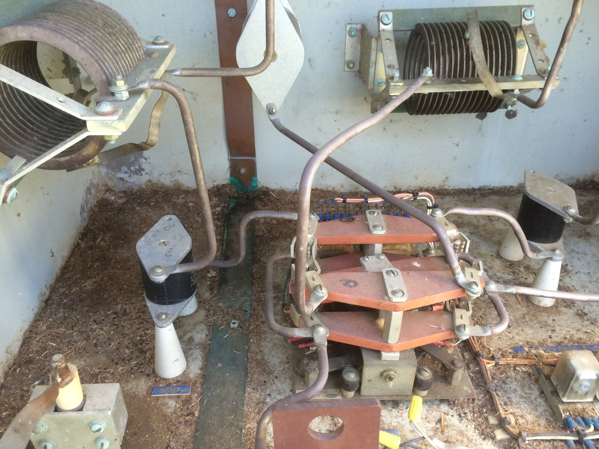
In all fairness to the current owner, this ATU reflects years of neglect. At some point, mice made a home in there and created a mess. The ATU smells of mouse shit, piss, and mothballs. It is full of mouse droppings, grass seeds, and fur. All of the ATUs in this array are in similar condition.
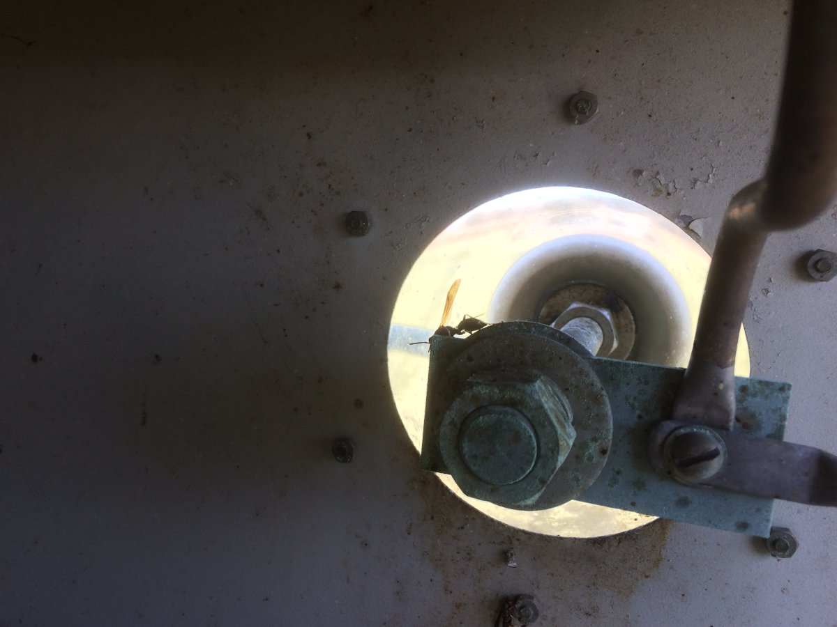
It was warm enough that the wasps were active, if not a little bit lethargic.
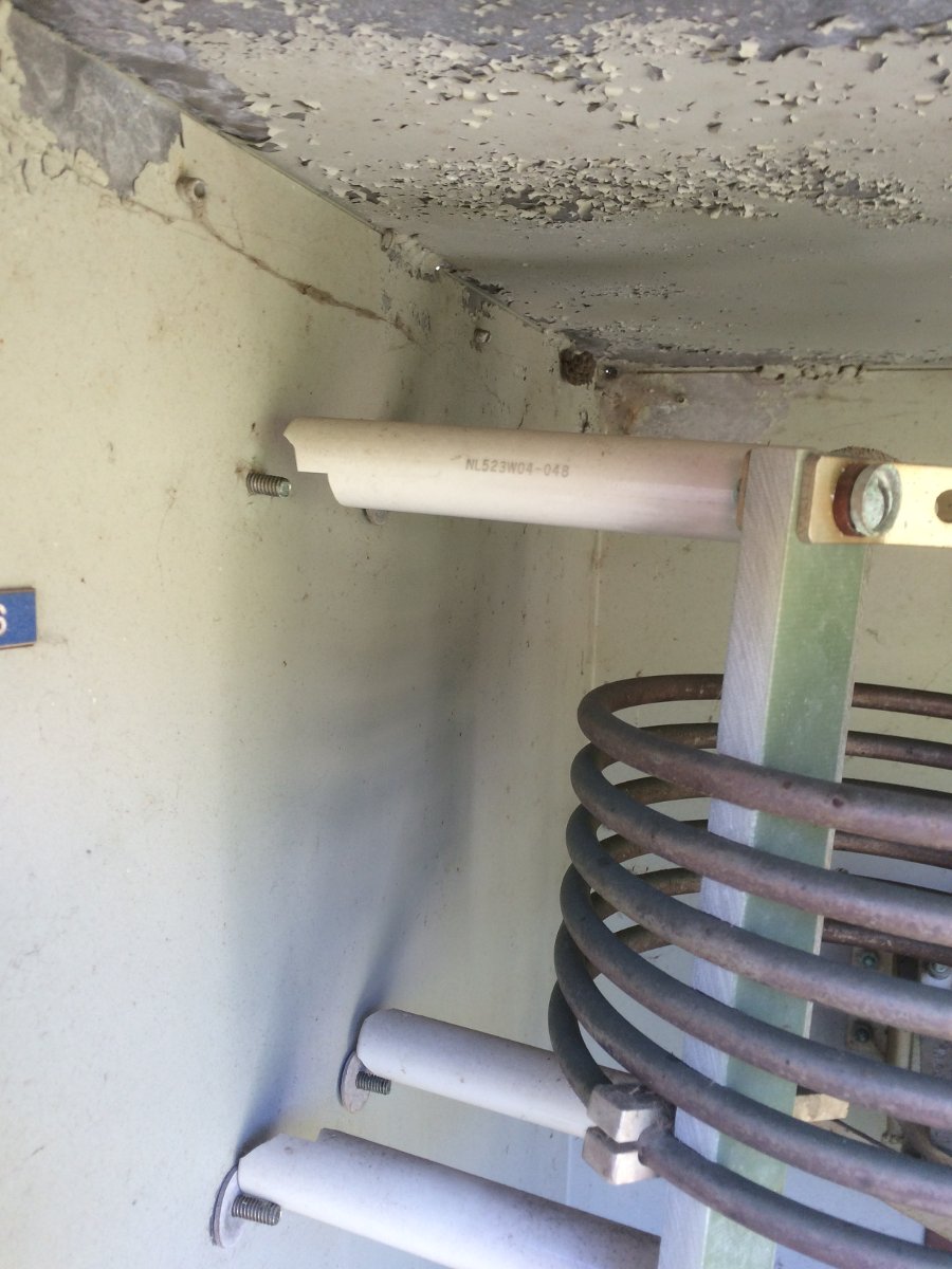
This coil is being held up by the tubing that connects it to other components. When the ATU was built, no nylon or cork bushings were used between the insulators and the wall of the ATU they were mounted on. Heat cycling eventually did all of the insulators in.
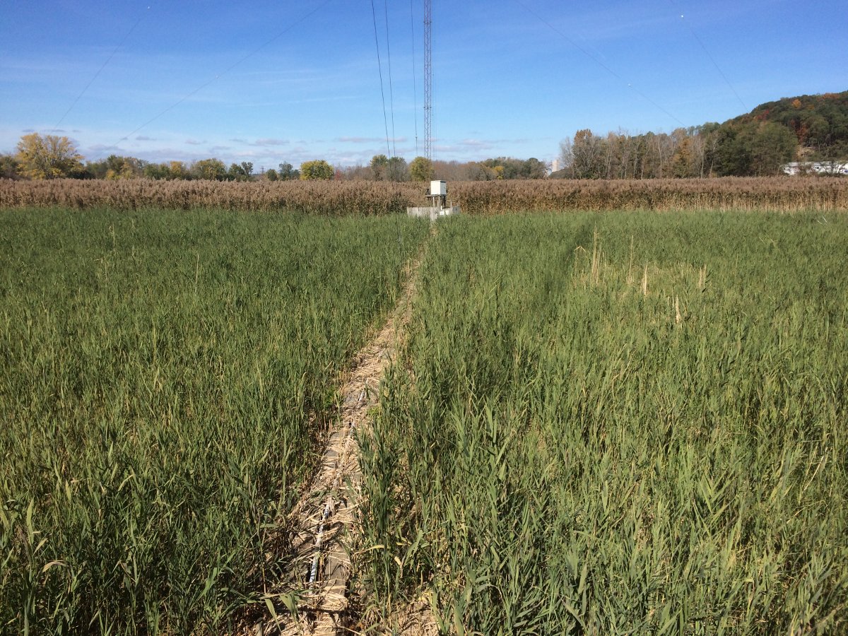
Catwalks to the other towers. At least the swamp grass has been cut this year, it is only four feet tall instead of ten.
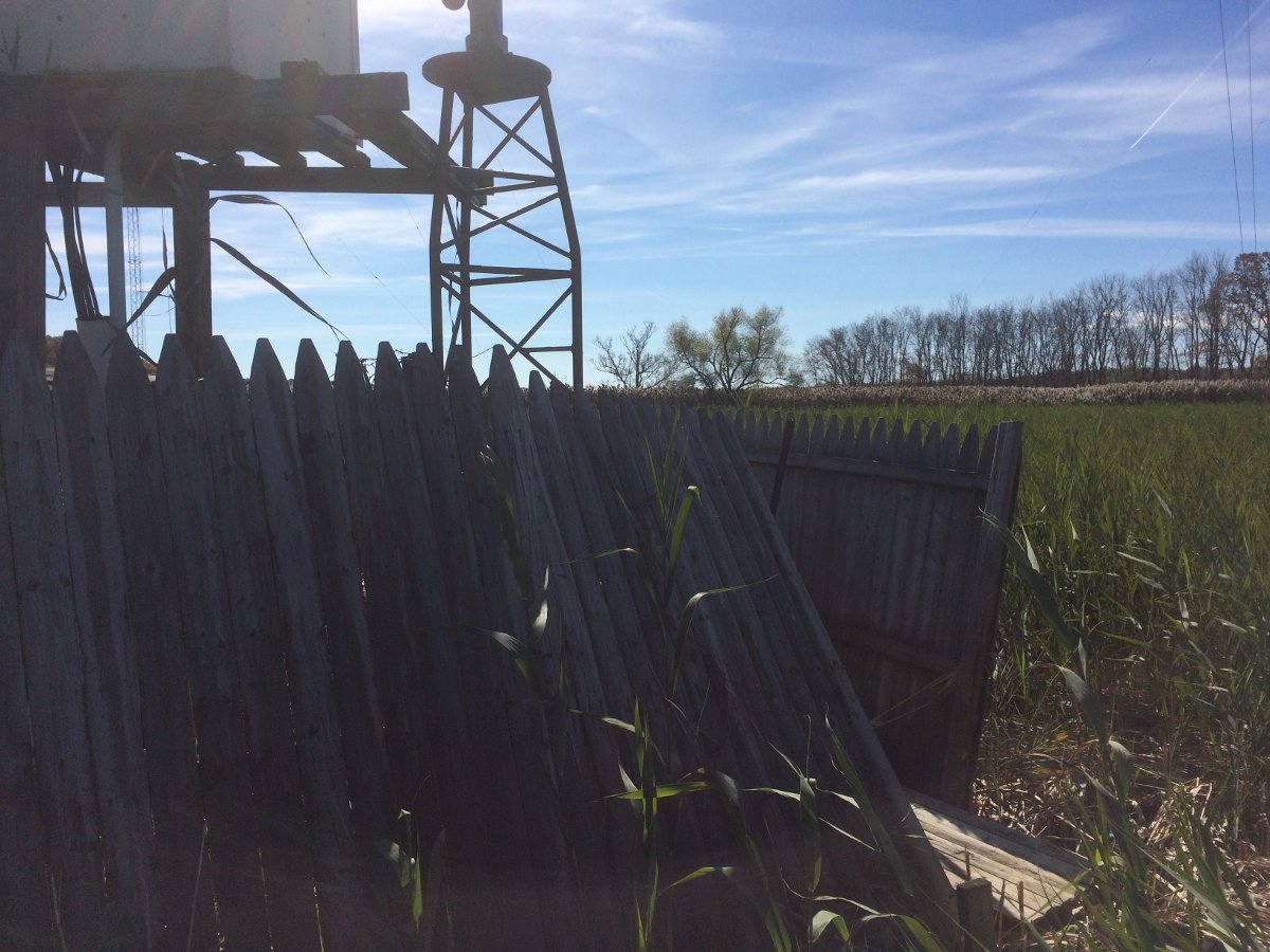
The tower bases are all elevated above the theoretical maximum water level. The ATUs are also up on stands with platforms build for maintenance access.

I cannot even blame the current owner, who has to spend considerable money to make repairs and upgrades to this site. It is very difficult and very expensive to catch up with deferred maintenance. Sadly, most AM stations we encounter have similar or worse problems.
I think it is too late to save many of these AM stations. The technical issues, lack of revenue, perceived poor quality, and lack of good programming are all taking their toll. At this point, the hole is so deep there is no hope of ever getting out. The FCC’s faux interest in “revitalization” followed by two years of stony indifference seems to be a final, cruel joke.
Microsoft: I am so done with you…
Except for the two applications that only run in Windows…
I lost the use of my Windows 7 partition on my laptop last week after a Windows update. They have been pushing Windows 10 for a while now, but I have ignored it because Windows 7 is just fine for me. I tried to ignore the latest nagging update and: Oh, joy! The computer is stuck in an endless reboot loop. Fortunately, I had a dual boot system and the Linux OS booted right up. Go figure! I was able to mount the Windows partition from Linux and recover all of my files. This is a good reason to have a dual boot system or keep a bootable thumb drive handy. At first, I thought I might be losing sectors on my hard drive, but no. It turns out, one of the files that changed during the update was corrupted. No big deal, I can reload windows and be back in business.
It will only take an hour or so. An hour that could be better used for something else, something akin to billable hours, which is how the mortgage gets paid. My computer is not a hobby, it is a tool. I don’t have time to play around with things for fun.
Then I thought, why bother? I am using Linux with no serious disruptions. In fact, it boots faster, runs faster, is more secure, and generally has fewer hangups. LibreOffice has all of the applications I need for general correspondence and business administration. I can run Win 7 as a virtual machine in VirtualBox as long as I can get the USB device I need to be recognized by Linux and then passed through to the virtual Win 7 OS.
So, to hell with Windows and all its nonsense. Goodbye, you inferior, expensive, and buggy piece of garbage. I will not miss you.
North Adams tower update III
And final.
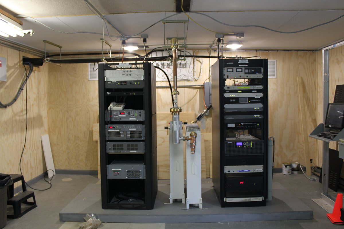
It has been a year and a half since the tower collapse in North Adams, Massachusetts. Since that time, WUPE-FM (Gamma Broadcasting), WNNI, and W266AW (New England Public Radio) have been operating with STAs at lower than licensed power. We have completed the installation of the combined antenna, filters, and combiners and now all stations are back to full power. Here are a few pictures of the transmitter room:
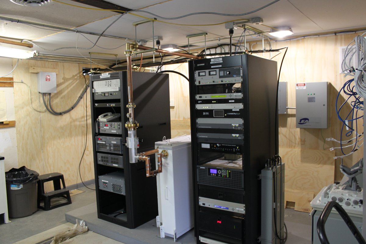
WUPE-FM (left-hand rack) is using a Crown FM-2000 transmitter, loafing along at 1,060 watts. WNNI (right-hand rack) is using a Gates Air Flexiva 2 running at 1,650 watts. Those stations are combined with a Shively Combiner:

We are still doing some grounding and neatening work behind the racks:
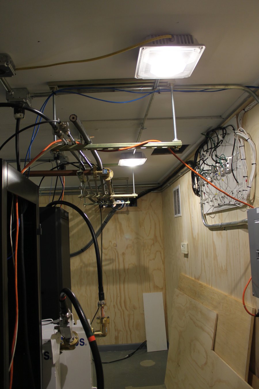
The Shively versa tune antennas that were mounted to the wooden utility pole as emergency antennas will be retained as backup antennas for both stations.
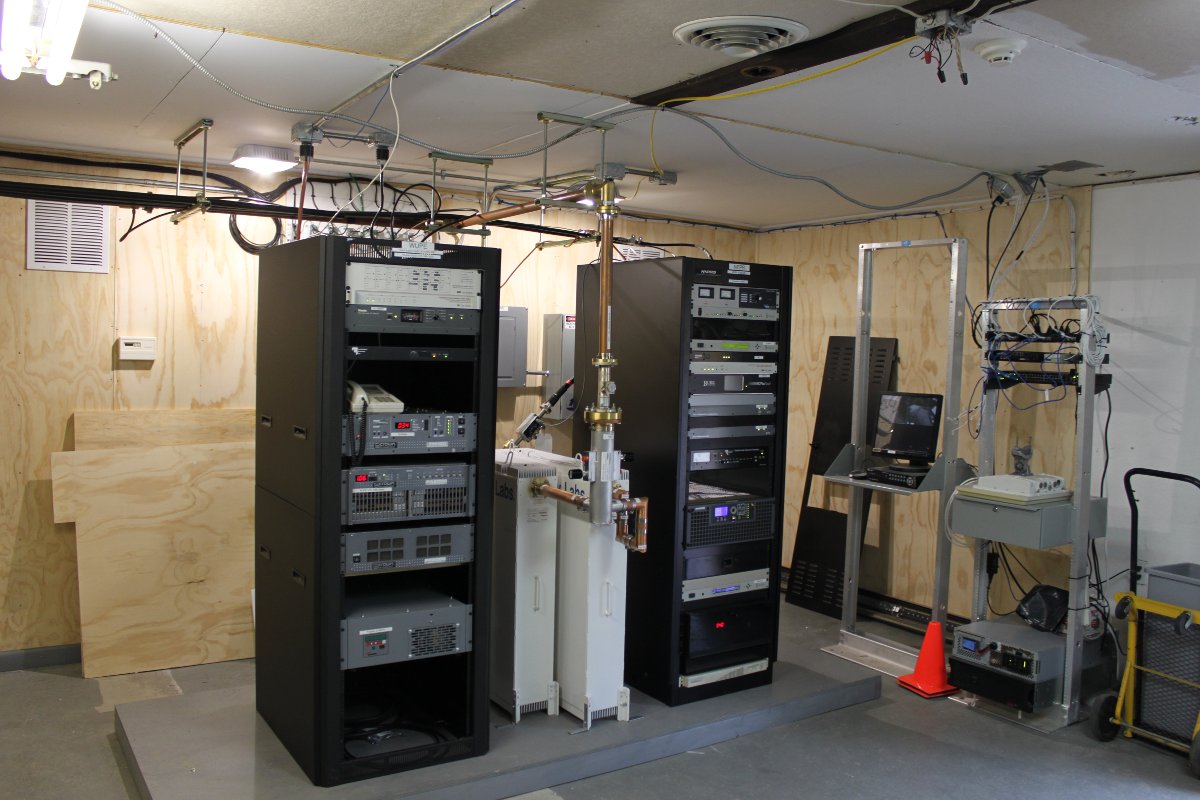
We share the room with Access Plus, which is a wireless internet service provider in western Massachusetts. Their stuff is in the open-frame racks to the right of WNNI.
Another view:
TL;DR: Tower collapses, and the facility is rebuilt better than before.