Occasional reader Scott asked for a picture of the inside of a BE AM output tuning network. I figured it might be helpful to make a short post about it.
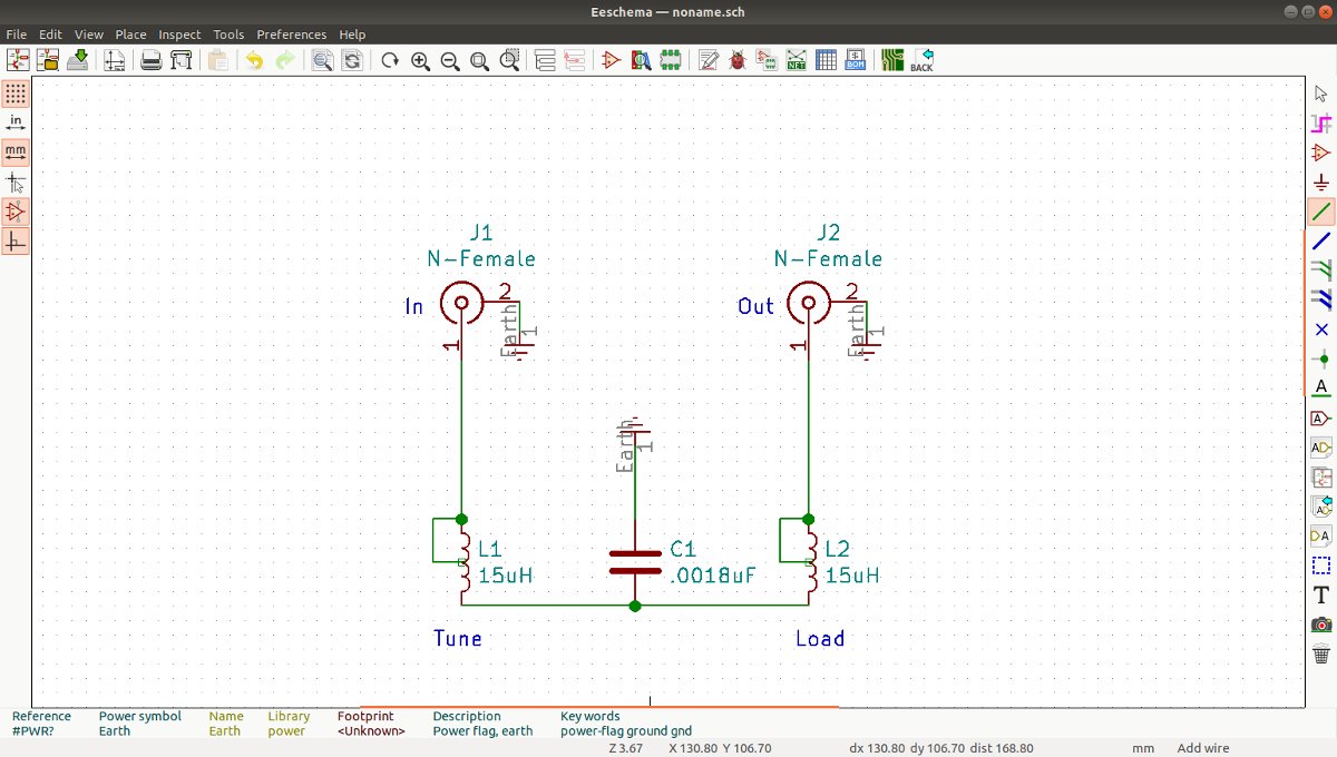
These things are pretty simple; a T network with a capacitive leg to ground.
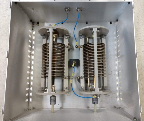
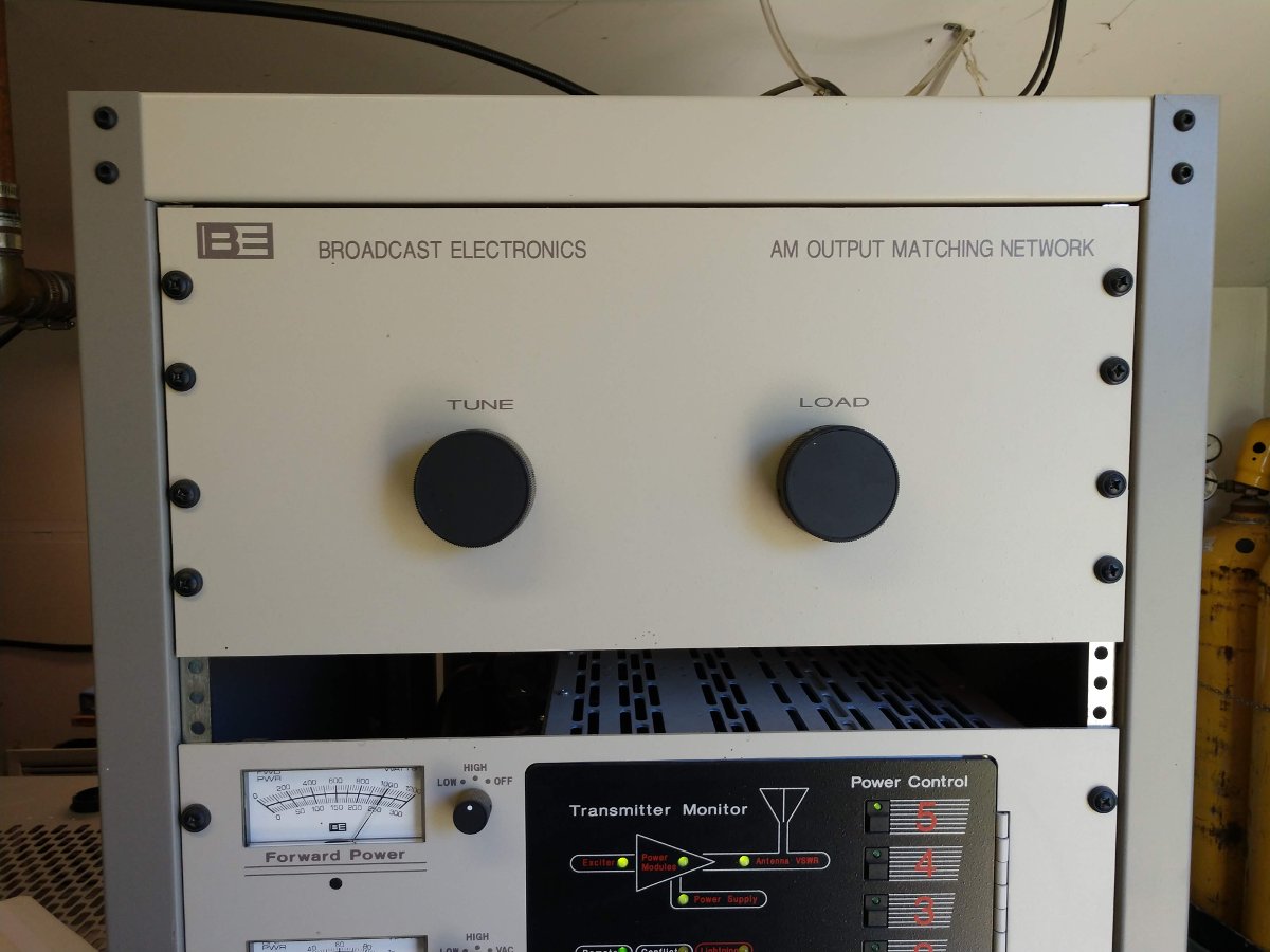
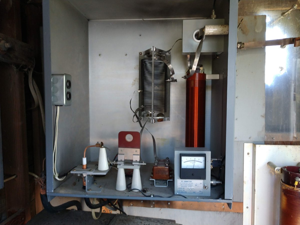
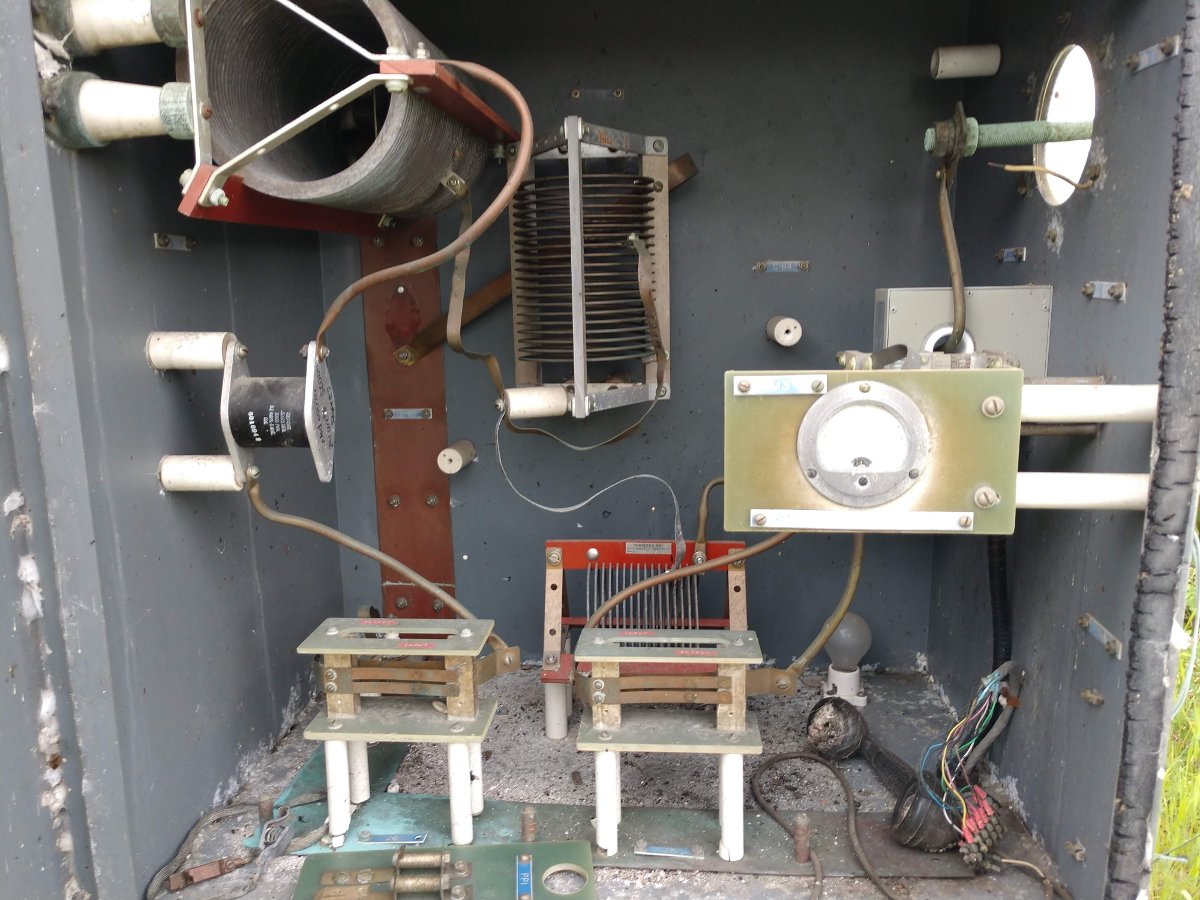
BE AM Output tuning network
This particular unit is for 1230 KHz. I believe the capacitor is frequency determined and they may also use larger inductors for lower frequencies.
BE AM output tuning network schematic
The inductors are Kintronic LV-15-20 (15uH 20 amp) and the capacitor is 0.0018 uF CDE 6KV 5.6 amp.
The issue with this particular unit is dirt. The inductors have round metal plates that roll along the inductor coil to make the variable inductor tap. Dirt has accumulated on the coil turns and on the inside of the plates. This, in turn, causes arcing anytime the Tune or Load controls are moved. A thorough cleaning should take care of the problem.
Working on another old AM station, this one is a simple Class C one tower on 1230 KHz.
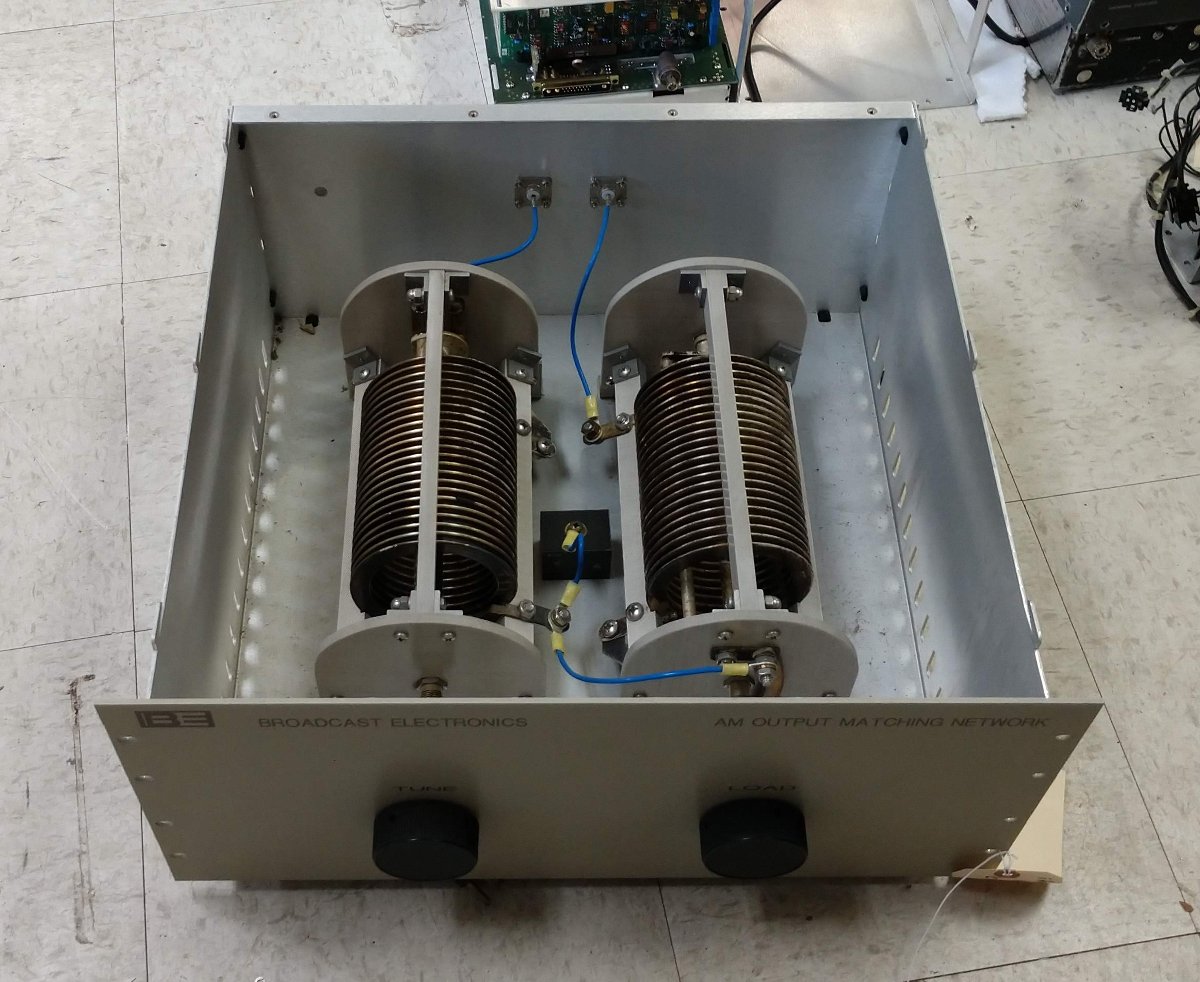
Broadcast Electronics AM Output Tuning Network
The main problem today was this BE AM output network unit between the BE AM1A and the ATU. This site has had some dirt difficulties over the years and the internal parts of this tuning unit arc at full power. I attempted to drive the ATU directly with the transmitter, which was a no-go.
Gates Radio 1 KW AM ATU, circa 1947
I took a look at the ATU, which is a pretty standard Gates 1 KW ATU from the late forties or early fifties. I have seen perhaps dozens of these things.
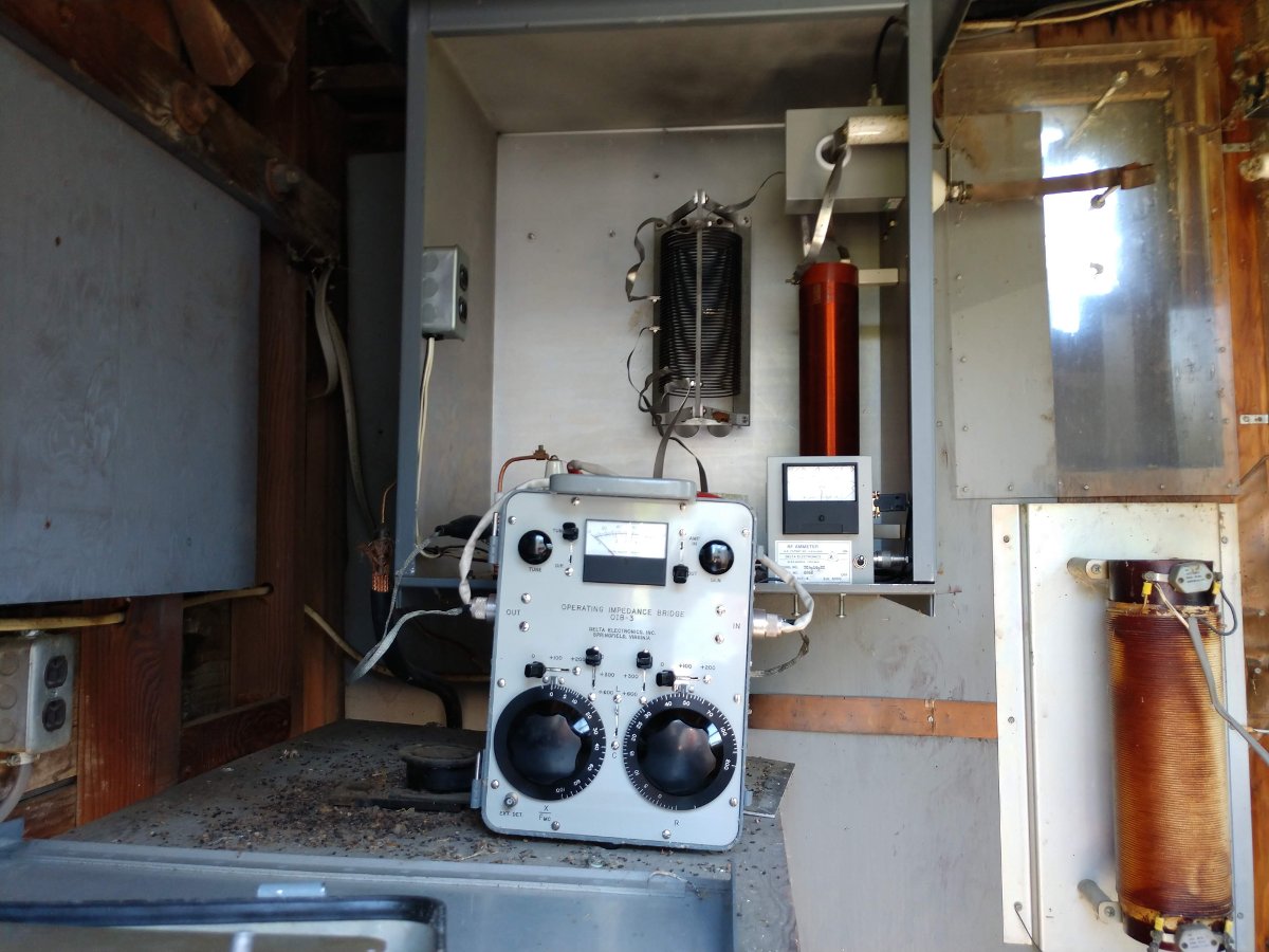
My first thought was that over the years, likely due to changes in the ground system, the base impedance has shifted away from its licensed values. However, a quick measurement of the base impedance shows it to be exactly at the licensed value, 17.3 ohms. The tower is 67 degrees tall so the impedance value is right in the theoretical norm.
I measured the input to the ATU, which showed 38 ohms with about 7 ohms of capacitive reactance. I can only surmise that it has always been this way. The transmitter in use before the BE AM1A was a Harris/Gates Radio BC-1G. That model transmitter will drive anything including an open transmission line.
Having the bridge on hand, I decided to retune the ATU for a better match. I put the bridge on the input terminals of the ATU and set it to 50 j0. Using the remote control, I turned the transmitter off and on while making small adjustments to the output strap on the coil until the resistance was 49 ohms with zero reactance. I would have gotten it to 50 ohms, but the strap on the output side of the coil would not stretch far enough to reach the proper spot on the coil.
Now the transmitter will run into the ATU directly at full power with about three watts reflected. The BE AM output matching network unit has been removed for cleaning and repairs. I will reinstall it once those repairs are completed.
It was ten years ago that I registered the domain name for Engineering Radio. A few days later, I put the first post up. It is still there. Those were different times for me personally and the business in general. There certainly have been trials, but it has never been dull.
Periodically, I go back through the posts and delete anything that is no longer relevant. I would estimate about 1/4 to 1/3 of the content has been deleted over the years. It is a good exercise to go back through and read what I wrote previously.
Currently, the stats are:
787 published posts, there are a few in the wings waiting to be finished
4459 comments
Approximately 200 page views per day
170 RSS feed subscriptions
I lost the country counter, but I believe the split is still about 60/40 US readers vs other countries.
I will continue on with this thing for as long as I feel it is worthwhile.
Yesterday I took, what I hope to be, my last walk across Pleasure Beach Island in Bridgeport, Connecticut. The task at hand was repairing the antenna array for WICC. There turned out to be several issues that were addressed in turn.
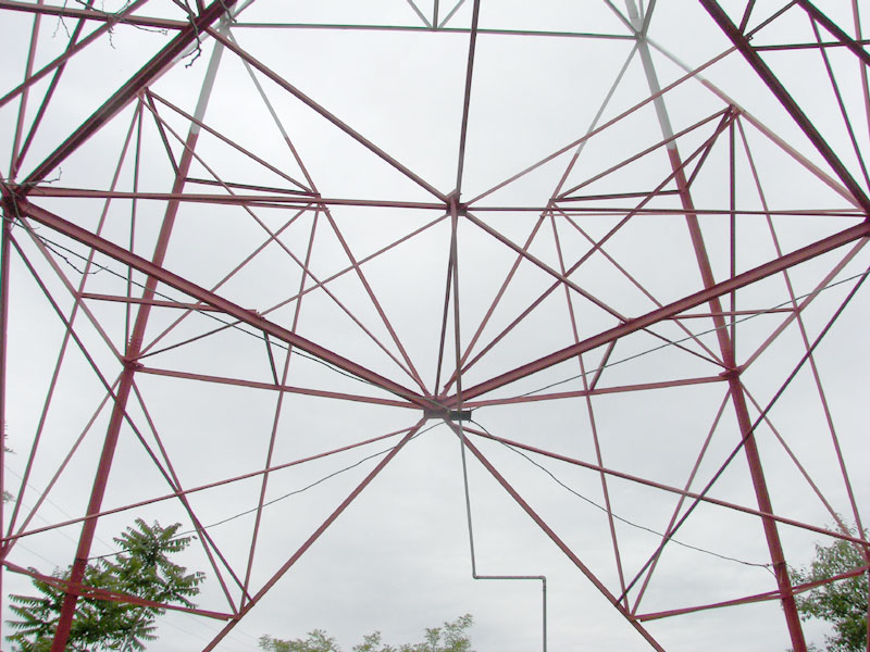
WICC tower feed point, courtesy of NECRAT
The trouble started when the feed line between the ATU and the tower became disconnected during a storm. That consists of a 1-inch copper pipe extending from the ATU feed through an insulator up to a brass plate suspended between the four tower legs by hard-drawn single 0 copper wire. The feed line separated at the brass plate which, unfortunately, is approximately eighteen feet in the air.
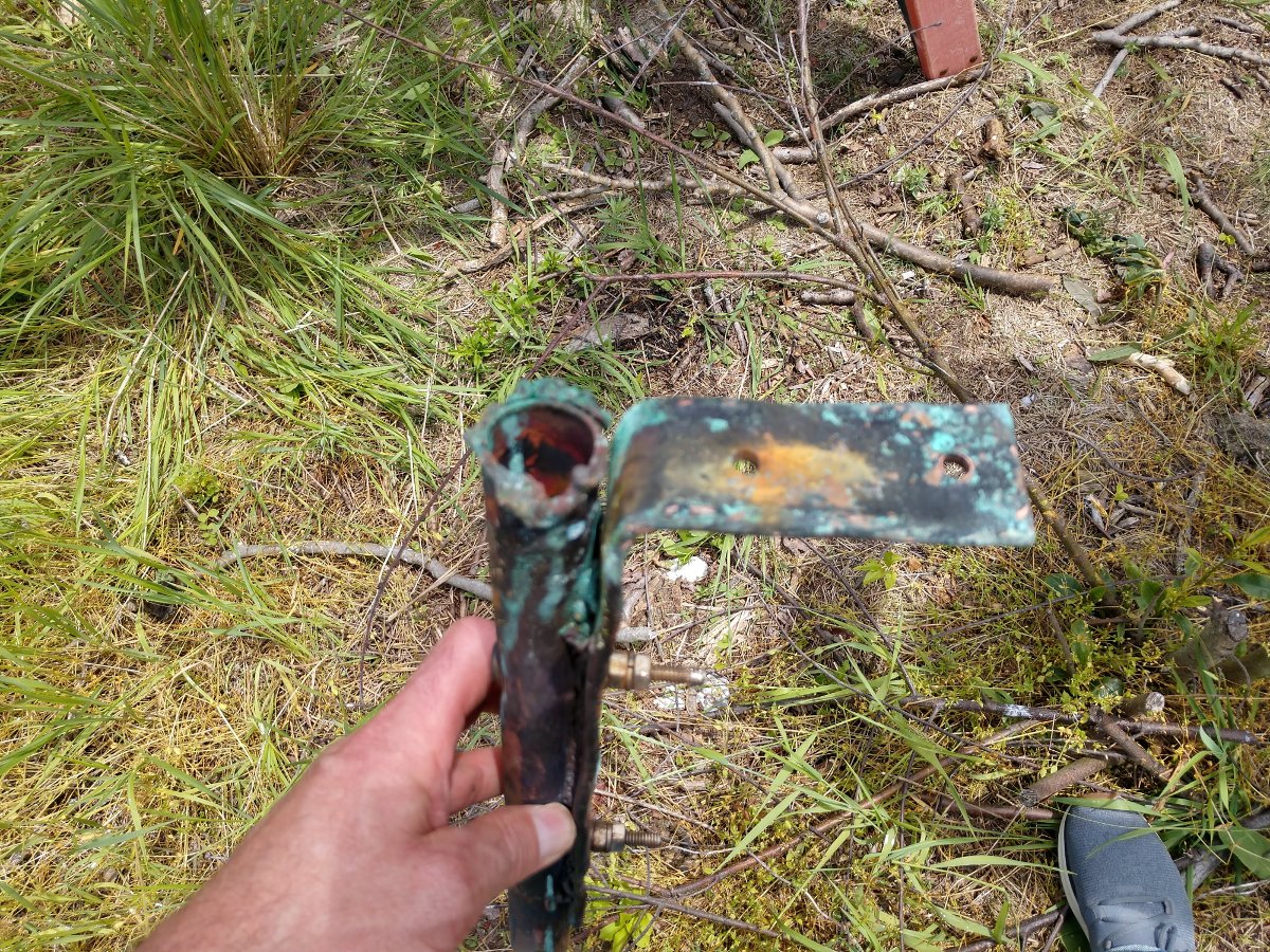
North Tower feed point connection, cold soldered
The feed line was repaired, but not effectively. By the looks of the picture, the brass plate never got hot enough to accept the solder.
After the feed line was re-repaired, other issues became apparent. The base impedance of the tower was still off and the array was still way out of tolerance.
It was noticed that several bypass capacitors on both of the tower lighting chokes were blown open. Those were replaced and the tower lighting chokes were checked for shorted turns. While it is always nice to replace burned-out parts, this did not correct the problem.
Finally, we were back at the base of the tower with the defective feed point and a decision to grab the pipe and give it a good shake to see if it came apart again. It did not, but then I realized that that tower was supposed to be back in the circuit and I did not receive any RF burns for my carelessness.
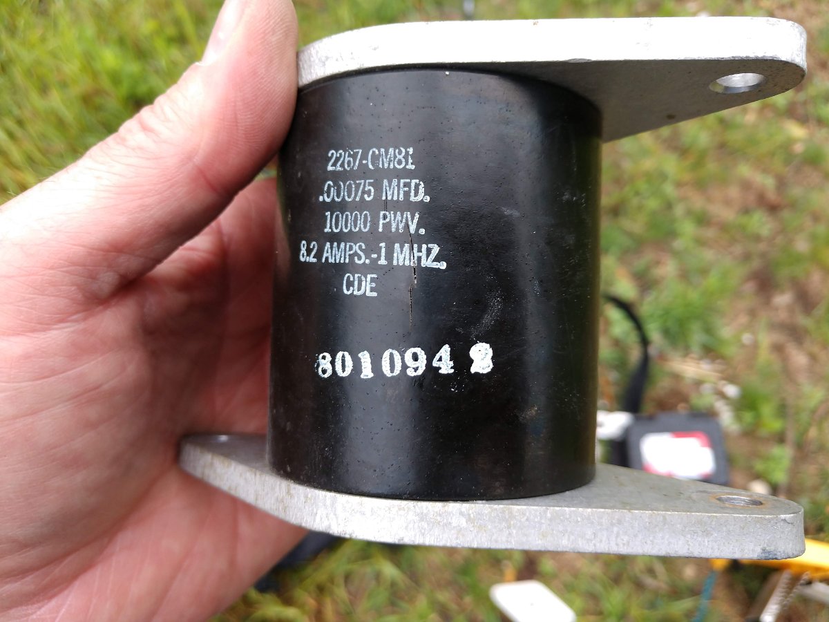
We dug into the ATU and discovered that the input capacitor was marginal and there was a large crack in it. The output capacitor seemed to be completely open. The base current that we were seeing on the base current meter was being induced by the other tower. It all began to make sense.
Bad Capacitor
The parts were ordered and shipped and I made another trip out to install them myself.
Thus, on this particular day, I had my tool bag, an OIB-3 with fresh batteries, my cordless drill, drill bits, and three type 294 mica capacitors. I took the drill because the new capacitors were quite a bit larger than the old ones, so I needed to move the stand-off insulators to remount them.
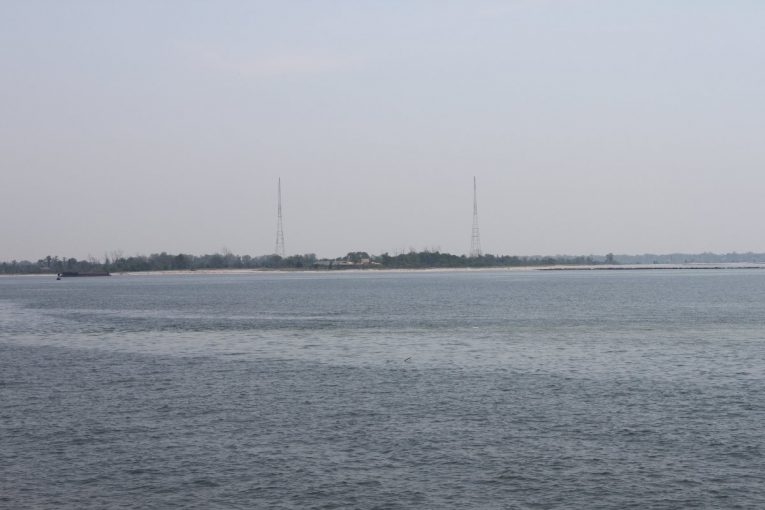
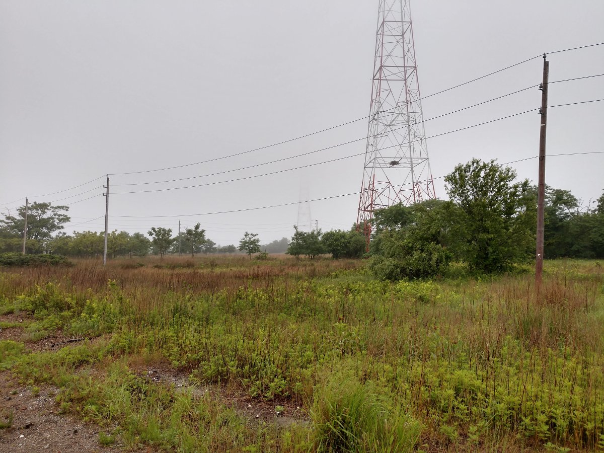
Pleasure Beach pier, foggy day
The walk from the end of the dock to the transmitter site is approximately 900 meters or 0.55 miles, according to google maps. On a nice day, it is a pleasant walk. On not-so-nice days, it can be less so. It was foggy with light drizzle. Not enough to get wet right away, but enough to get slowly soaked while working on the ATU repairs.
WICC square base self-supporting towers, manufactured by Milliken Tower, circa 1928
With the new capacitors installed, I needed to adjust the array back into tolerance, which didn’t take too long. I made a short video of the station running at full power showing the antenna monitor readings for both the day and night patterns. Then packed up and headed back to the dock.
My ride is here
I wanted to take a set of monitor points, but the FIM-41 had been moved to another location. That was fine, I was getting pretty uncomfortable in my wet clothes, so I headed home.