Or, it could also be phrased “A solution that causes more problems.” Radio World, once again, has a good article on the consequences of increasing IBOC power of the FM hybrid system. Especially telling is figure 24, a fuzzy 400 Hz sine wave showing how much distortion is added to the analog signal by a mere 4% HD signal. I’d be especially interested to see the results of the full 10% now allowed.
Naturally, HD proponents will cry “But this is only temporary! Wait until the transition to all digital!”
Bunk.
If HD radios were indeed flying off the shelves as iBiquity claims, and if the public expressed interest, okay, maybe. Clearly, that is not the case. The only thing that HD radio is doing is creating more interference. Period. More interference to the parent station and more interference to the adjacent channels all for an audience that does not exist. Another way to put it: NOBODY IS LISTENING. One of the stations that I service had a Harris Deathstar go offline for four days. NOT ONE PHONE CALL, NOBODY CARES!
The public did not perceive a technical problem with analog FM broadcasting. Of course, that can always change as the band gets filled with interference.
Let’s see where FM IBOC stands:
Rolled out with 1% digital power vs analog carrier, the system was found to lack building penetration and generally performed poorly in mobile listening environments (NPR labs study, Nov 24, 2009)
FCC allows up to 10% digital power vs analog carrier to overcome these problems, a few stations implement some type of power increase
This shows that self-interference is the largest problem IBOC needs to fix, one that is un-fixable due to the laws of physics
The public yawns, turns on their iPod
IBOC is a failure, both in AM and FM bands.
We are watching the self-destruction of radio broadcasting in the US.
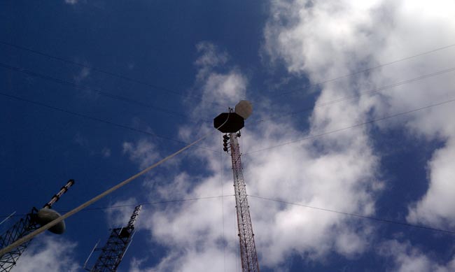
WSPK is located on North Mt. Beacon, which is the highest point for miles around. It has a fantastic signal. The site is a little difficult to get to, however, especially in the winter. In previous years, the road has been impassable four months out of the year. Some engineers have hired a helicopter to get up there when the snow is deep. For that reason, it is important to keep the equipment in good shape.
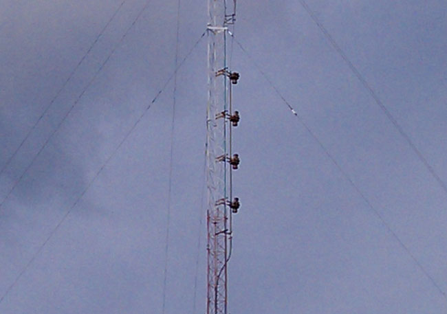
WSPK Shively 6810 antenna with damaged top radome
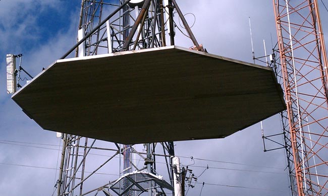
After last February’s snow/rain/ice storm, it was noted that the top antenna radome was missing its top. A tower climber was sent up to look at it and it was also discovered that the top bay was bent down and the element was almost cracked in half. A result of falling ice, likely from the big periscope microwave reflector (passive reflector) mounted above it.
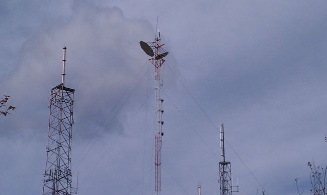
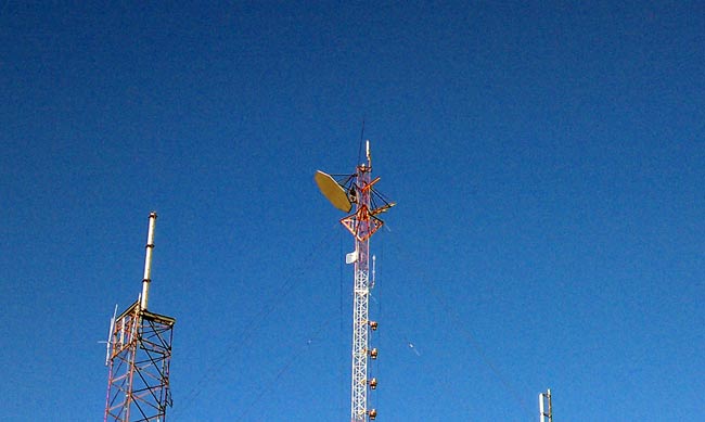
WSPK tower
The periscope reflectors went out of service in 2007, but the tower owner did not want to pay to take them down, thus a problem was not being solved. It was decided to replace the 25-year-old Shively 6810 antenna with a new one, during which work, the radio station would pay to remove the reflectors from the tower. In exchange for that work, the radio station would then be able to repair and remount the old Shively antenna below the new one, thus having a backup antenna. Problem solved, except for, you know: The actual work.
The tower and the periscope microwave system were installed in 1966, operated on 12 GHz, and were used by the Archdiocese of New York to relay their educational television programming from their Yonkers headquarters to the various schools in the Hudson Valley. Sometime around 1975 or so, the FCC mandated that periscope microwave systems could no longer be used due to all the side lobes and interference issues they caused. They were to be taken out of service as soon as possible. The Catholic Church, being a multi millennial organization figured “as soon as possible” meant within the next fifty years or so. Anyway, somebody else needed that frequency, therefore in 2007, they bought the Archdiocese a new digital microwave system.
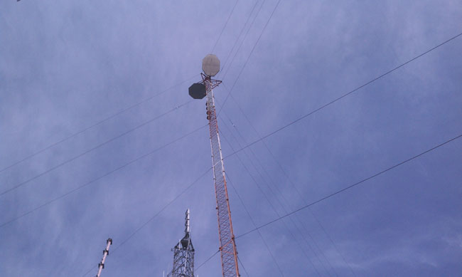
The problem with the reflectors; they are big. They are also heavy, and present a huge wind area. They are also 300 feet up in the air.
WSPK tower periscope reflectors seen from ground level
Finding a day with lite winds on top of Mount Beacon can be a problem. Luckily, the weather was with us. Still, it took a while to get this work moving along. The other consideration is RFR and tower climber’s safety. There are two digital TV stations, WSPK, several cell carriers, something called “Media Flow,” and a bunch of two-way radio repeaters. The main concern was WSPK, the DTV, and Media Flow since the top of this tower is right in the aperture of those antennas. All either went way down in power or off the air while this work was ongoing.
Rigging a gin pole and getting it to the top of the tower was a chore. The gin pole needed to be threaded through those torque arms like a needle.
Gin pole
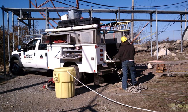
The tower riggers truck had two winches, one a basic 120-volt capstan, the other a hydraulic winch in the bed of the truck with 1/2 inch steel cable.
Tower rigger’s truck
The bolts holding the reflectors in place had to be cut with a saw, you can see the tower climber working on the left-hand reflector, which gives you an idea of size. If this reflector were to fall off the tower, chances are good that major damage and or injuries would result on the ground. Proceed with extreme caution.
Cutting bracket mounting bolt on periscope reflector
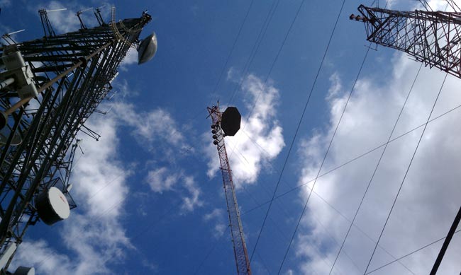
Carefully lowering reflector past Shively 6810 FM antenna and Scala PR-950U microwave antenna. During this phase, the tower climbers had to push the reflector out away from those obstacles with their legs. You can see the gin pole at the top of the tower.
Lowering Periscope reflector
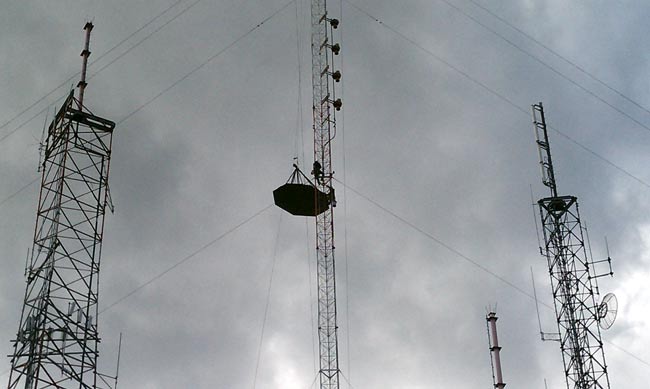
Another view:
Lowering reflector
Another view:
Lowering reflector
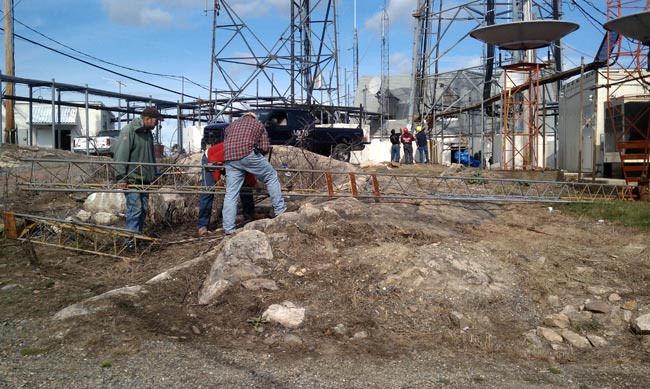
Almost down to the ground. This measured 15 by 10 feet and ended up weighing 830 pounds.
Reflector almost to the ground
One down, one to go. I can’t believe those gigantic things were at the top of this tower, on the top of this mountain for 43 years and the tower is still standing. This is going to change the appearance of the mountain top from down below. For years, it looked like a pair of mickey mouse ears, now it will only look like a tower. I wonder what the environmentalists will think.
I will make a second post with the antenna pictures as this one is getting a little long.
Broadcasters historically have tried to remain on the air during emergency events like major storms, earthquakes, and other forces of nature. Oftentimes, commercial power is interrupted, and thus, the backup power generator is installed. Propane-powered generators for medium duty (power up to 45 KW) are popular because of the decreased environmental hazards, availability and expense of fuel, and ease of maintenance and repair. This sized generator can run the critical loads of a studio facility or a transmitter site with TPOs between 5 and 10 KW.
Katolight 45 KW generator w/outside housing
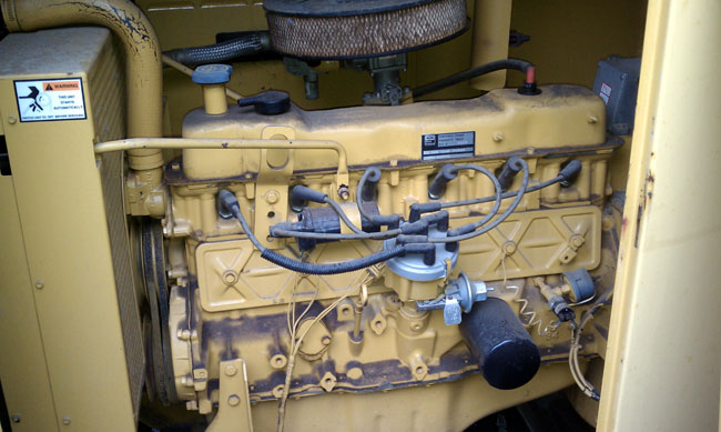
Most propane generators use a gasoline engine modified to use propane. These generators can also use natural gas, however, because natural gas has slightly less energy, the generator’s service rating is reduced by about 10 percent.
Ford inline 6 cylinder engine
The biggest error I consistently see with propane generators is improper fuel tank sizing. It might seem just fine to plop a 500-gallon tank down next to a 45 KW generator and expect everything to be just fine. 500 Gallons may sound like a lot of fuel, but the more important consideration is tank vaporization, that is to say, how fast the liquid propane can be removed from the tank for use. Propane fuel companies should be able to size these things correctly, most of them have books and charts that tell what capacities and sizes are needed. However, as a general troubleshoot guide, the following information is provided:
Generator manufacturers will specify how many BTU per hour a generator will require under full load. If not, these are some conservative rules of thumb:
For every 1 KW of electrical generation, 2 horsepower of the engine is needed*
Under full load, each horsepower will consume 10,000 BTU per hour*
Propane has 92,000 BTU per gallon
Propane weighs 4.2 pounds per gallon
*Note: These are not the figures you will find in your engineering handbooks, they are adjusted for generator winding and engine efficiency.
Propane Tank Vaporization Rates (Continuous BTU/hr vs volume at tank temperature):
Size propane in a tank (assumes 1/3 full)
Maximum continuous BTU/hr at degrees F
0°
20°
40°
60°
70°
120
129,600
188,640
247,680
308,160
338,400
150
146,880
213,790
280,700
349,200
383,520
250
253,800
369,400
485,000
603,480
662,700
325
321,300
467,670
614,000
763,900
838,900
500
396,270
567,700
757,300
942,240
1,034,700
1000
708,480
1,031,230
1,353,980
1,684,600
1,849,900
1450
816,120
1,253,400
1,645,690
2,047,550
2,248,480
Note: Tank vaporization depends on fuel level, tank temperature, and withdrawal rate. The above chart is a conservative generalization and represents a safe median value.
If a propane tank cannot vaporize fuel fast enough, the generator will begin to run lean, eventually overheat, and shut down. The vaporization rate depends on the tank temperature, which drops as fuel is withdrawn. For the above-cited 45 KW generator called to duty after a severe winter storm, the tank would need to vaporize: 45KW x 2 HP = 90 HP. 90 HP x 10,000 BTU/hr = 900,000 btu/hr. A 500-gallon tank is too small for that size generator.
As the tank temperature drops a propane tank can develop frost on the outside of the tank, even on a hot summer day, which compounds the problem.
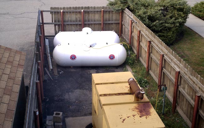
The correct size tank for a 45 KW generator is 1000 gallons. This can also be two five-hundred-gallon tanks connected in parallel via a high-pressure line.
45 KW propane generator with two 500-gallon tanks
Also note, the generator’s radiator is facing the tanks so that when the unit is running, hot air is blowing on the tanks, warming them up. This particular generator is about 25 years old, which is why it looks a little worn. It still carries the load and mechanically is in sound condition.
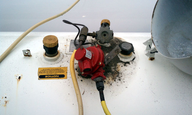
Most propane fuel systems have two regulators; one high-pressure regulator on the tank, which takes the variable tank pressure and steps it down to about 10 PSI, and the vaporizer which steps the pressure down to a few ounces per square inch (or inches of water column) and adds air creating propane gas for the generator to burn.
High-pressure propane tank regulator
It is important that the vaporizer be mounted above the snow line and that there is a little screen on the air intake, otherwise, mud wasps will build a nest in the air intake and the next time the generator is required to run, it won’t start.
Low-pressure propane regulator/vaporizer
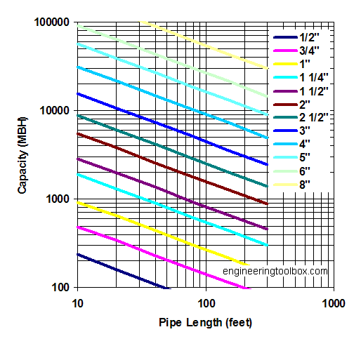
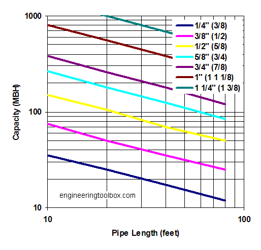
Fuel piping is also a concern, if the low-pressure lines are not large enough to handle the required BTU, the generator will run lean, creating the same problems as an improperly sized tank. Different piping has different capacities, see the following charts:
WE2XRH looks like an Amateur radio call sign but it is actually the call sign of an experimental short wave station in Alaska. Transmitting DRM on 4.85 MHz, 7.505 MHz and 9.295 MHz with a Near Vertical Incident Skywave antenna system, they hope to cover all of Alaska and almost nowhere else with shortwave broadcast.
WE2XRH DART coverage with NVIS antenna system
This license was granted for two years in August of 2008 and renewed again this September until July 2012. According to the website Nextgov.com:
The company told FCC that its initial tests would be funded by and conducted for the Defense’s Joint Electromagnetic Technologies program, a classified operation whose mission is to develop technologies for use by special forces and intelligence units.
Defense also will supply surplus transmitters from the closed, Cold War-era Over the Horizon Radar, located in Delta Junction. The radar system bounced shortwave signals off the ionosphere to detect aerial targets, such as Soviet bombers, at ranges up to 1,800 miles.
The transmitters are 100 KW Continental HF units, which for this applications are running about 20 KW. According to this Yahoo Groups posting, several Japanese shortwave DXers have received the station in late 2009, but nothing recently. I shot an e-mail off to their information address, but did not receive a reply.
On High Frequency (HF) NVIS has been used for several years where line of sight VHF communications are not possible. Soldiers during the Vietnam war noticed that if a vertical whip was bent over so that it was horizontal to the ground, the signal strength was slightly less but the signals were much less prone to fading.
Near Vertical Incident Skywave antenna angle vs. distance
In this case, WE2XRH is using a crossed dipole antenna which generates a circularly polarized field. With traditional HF skywave, polarization is not a factor since the ionosphere usually causes some field rotation anyway. It is interesting that the system had this design consideration.
The NVIS is a novel approach and it may work on Medium Frequency (MF) during the night time, but daytime coverage would still have to rely on ground wave signal. The FCC has historically approached MF skywave as a secondary and unreliable transmission method. The idea being to reduce the antenna take off angle to as low as possible, hence the popularity of taller than 90 degree towers. There is good validity to that practice as mixing the ground wave and skywave components at a receive antenna will cause multipath fading.
Setting aside a new broadcasting frequency segment, say 1.6 – 1.8 Mhz, a system could be designed to transmit DRM by using groundwave during the day with a traditional 90 degree tower, and NVIS at night with a horizontal dipole antenna. Then never the two should meet. The night time NVIS system would have a small ground wave component, out to a couple of miles. In addition to that, the night time NVIS system can run on an adaptive power system, when propagation conditions are poor, more power can be applied to the antenna input and in better conditions, power reduced in accordance with a remote receive monitor that reports the Bit Error Rate (BER) back to the transmitter controller.
The best NVIS antenna is the 1/2 wave dipole positioned between 0.1 and 0.2 wave lengths above ground. In the 1.6 to 1.8 MHz band, that equates a half wave dipole antenna 260 to 292 feet long mounted between 66 to 90 feet above ground level.
This would have many advantages over the current directional antenna based MF broadcasting system currently deployed. The current system is based on pushing potential harmful signals away from a station that was licensed to the same frequency (or an adjacent frequency) earlier. This puts the onus for proper operation on the broadcast license holder. Most don’t have the know how or resources to insure that a n AM directional is operating properly. I would estimate at least half of the directional AM antennas in this country are out of tolerance. With a NVIS based night time antenna system, coverage areas would be assigned much like an FM allotment.
The BBC conducted medium wave DRM tests in 2007 with satisfactory results during the daytime, but poor reception at night time due to co channel interference. That is why DRM will not work on the current AM broadcast band and if digital radio is to be broadcast on MF, a new frequency band would be needed.