WEBE WICC studio build out

You know those fancy new facilities pictures with the accompanying article you can normally find in the trades?  The article usually expounds on how this guy made the decisions on purchase then these guys worked hard and pulled it all together.  Here is the work hard and pulling it all together story.

WEBE and WICC have been in the same studio building for several decades.  The Pacific Recorders and Engineering equipment, while great, is tired and worn out.  On top of that, an F1 tornado ripped the AC units off the roof last June, ripping the membrane and doing extensive water damage to the facility.

The cleanup/water damage mitigation took some time.  All of the carpet and ceiling tiles needed to be replaced.  The walls needed to be resurfaced with new drywall.  In some cases, modifications such as removing a storage closet from the engineering room, moving a door, and building a new talk studio and WICC control room needed to take place.  In short, lots of dust, dirt, and disruption to the station equipment and staff.  It has not been trouble-free, as several times computers and consoles failed due to age and dirt.

Sometime about the beginning of December, new equipment and furniture began to show up and the project was underway.
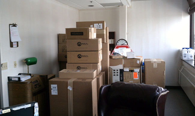
Cumulus Bridgeport new equipment

All of the new equipment was stored in the program director’s office.  Heh, the program director’s office.

Cumulus Bridgeport new rack room

A new rack room was designed around the old one.  The old racks are out of the picture to the left.  The original rack room had a door into the hall, that has been replaced by viewing windows, the door has been moved to the engineering office, next door.  I kind of like the windows, it lets visitors see the fancy computers but keeps them out of the room itself.
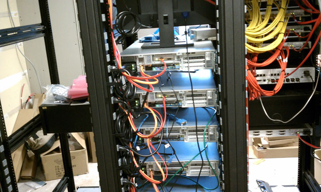
Cumulus Bridgeport Op-X servers

The existing automation system is being replaced by Op-X.  This is the business end of the Op-X audio servers.  All of the network connections are Gigabit using Belden Mediatwist (1872A) Category 6 cable.

Cumulus Bridgeport wire wall

All the wiring from the studios and racks are brought to this wall.  The terminations are Krone LSA-PLUS blocks.  AES/EBU digital and analog audio is run on Category 5e cable.
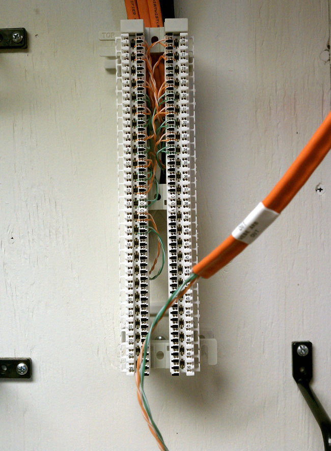
Cumulus bridgeport wire wall Krone block

Krone LSA-PLUS termination block with Belden Mediatwist cable.  All rack and studio wire runs are terminated on this style block.  Notice the wire labels, every run is labeled with both termination ends and use.  Mediatwist cable is fairly easy to work with, the pairs are bonded, so a special tool is recommended to quickly separate the wires.
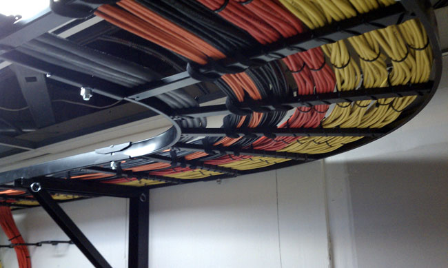
Cumulus Bridgeport wire tray

Wire tray between the racks and wire wall.
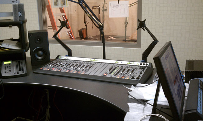
WICC new Axia console installation

The new WICC control room and talk studio.  The Axia consoles are pretty slick.  They are not a true mixing console in the traditional sense, they are more like a control surface.   Most all of the audio inputs are in the rack room, however, the microphones are digitized in the studio and sent over an IP network to the rack room.   All input and output channels are computer configurable and remote controllable.  Console inputs also have onboard mic preamps and full processing.

Cumulus Axia console set up

Axia console control software.

New WICC talk studio furniture

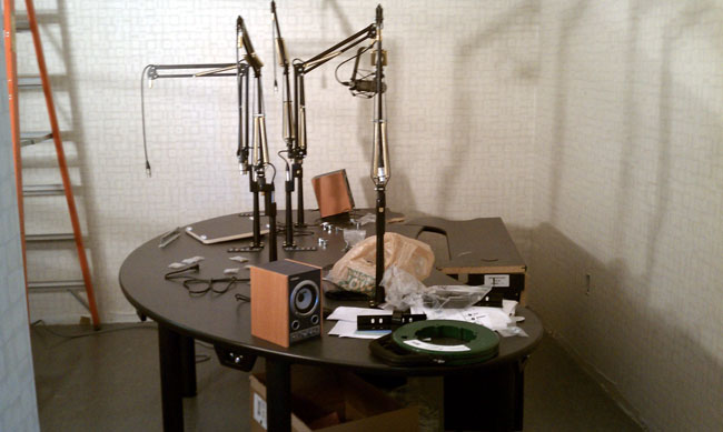
The new talk studio set up.  This is located where the news room used to be.  In order to stay on the air and maintain the old studios, a sort of musical chairs system needs to be played.  In the end, the WEBE studio and one production room will end up where they started, everyone else will be in a new space.  The news room will end up where the current WICC control room is.
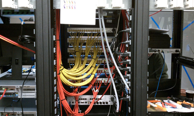
Cumulus Bridgeport network switches

Network audio switches.

Cumulus Bridgeport network patch panel
Cumulus Bridgeport network patch pane

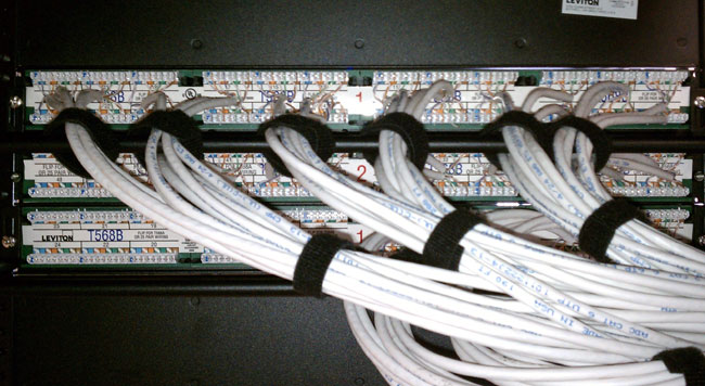
Network patch panel, notice the T568B markings.

Currently, the program directors are loading all there material in the Op-X system.  The time schedule is to transfer WEBE into a temporary studio in about two weeks.

More updates as the project progresses.

Update: The new Axia equipment and Op-X automation is on line as of 2/24.   More pictures to follow.

Update 2: For more information on how the Axia consoles are made, check out A broadcast console makers perspective.

Update 3: More pictures:
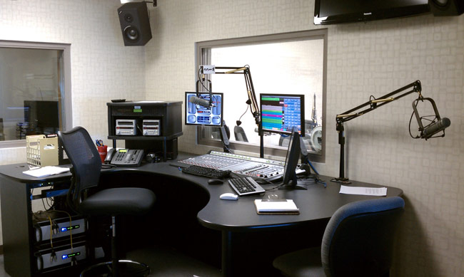
WICC new studio with Axia console

WICC studio is nearly done, just a few odds and ends here or there.   This is located where the former talk studio was located.

WICC talk studio
WICC talk studio

WICC talk studio, host and four guest positions.  This is located where the former news room is.
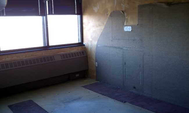
Former WICC air studio, gutted

This is the former WICC control room.  It has been gutted and several walls are being removed.  This will become the permanent WEBE control room when it is finished.
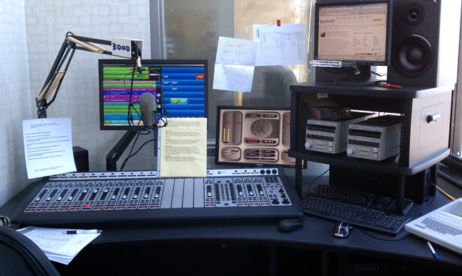
WEBE temporary control room

WEBE temporary control room.

WEBE old control room, gutted

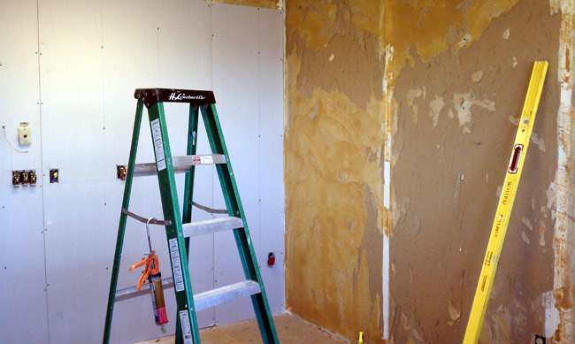
The former WEBE control room, gutted.  All the carpeting has been removed and 1/4 inch drywall is going over the old, glue encrusted drywall.  This room will become a production room.
WEBE WICC rack room
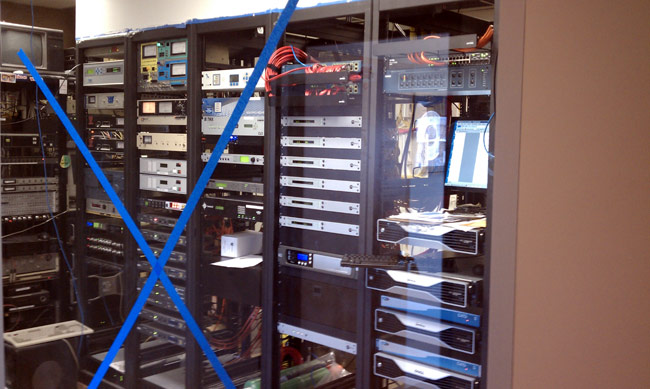
WEBE WICC rack room

WEBE WICC rack room viewed from the hallway, approximately where the door to the room used to be.  The old racks to the left are being stripped out and removed.  All of the stations are now on the air from the new racks.
Which do you prefer, GPS or 4G data?

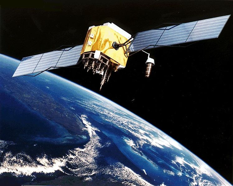
Block II GPS satellite

In some locations, it is apparently going to be an either-or situation if this is to be believed:

Representatives of the GPS industry presented to members of the Federal Communications Commission clear, strong laboratory evidence of interference with the GPS signal by a proposed new broadcaster on January 19 of this year. The teleconference and subsequent written results of the testing apparently did not dissuade FCC International Bureau Chief Mindel De La Torre from authorizing Lightsquared to proceed with ancillary terrestrial component operations, installing up to 40,000 high-power transmitters close to the GPS frequency, across the United States.

Sound vaguely familiar?  Seems that LightSquared took a page from the iBiquity play book when it comes to dealing with the FCC.   The article goes on to say:

On January 26, the FCC waived its own rules (emphasis mine) and granted permission for the potential interferer to broadcast in the L Band 1 (1525 MHz—1559 MHz) from powerful land-based transmitters.

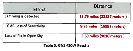
A little research on the LightSquared website shows they are rolling out an extensive L band 4G data network, not exactly what I would call broadcasting, at least not yet anyway.  GPS system inhabits 1559 – 1610 MHz, centered around 1575.42 Mhz in the L-band.  The signals coming from GPS satellites are very, very low, with the open sky signal around -130 to -135 dBm.  Indoor signals can be as low as -150 dBm.  Further, GPS receivers currently in the field were not built to operate in environments with high levels of RF energy on nearby frequencies.

So, who uses GPS?  Just about everybody, including the military, the aviation industry, broadcasters, and the general public.  Think about all the confused drivers who can no longer find their way to the grocery store without Tom-Tom.  By far, the biggest impact is likely to be the entire cell phone network, which depends on GPS for its multiplex timing.  It seems very likely that LightSquared network will be installed on existing broadcast and cell towers, right on top of the current cellular tenants.  Even if they work around this by providing better GPS receivers with high pass filters,  many existing consumer and aviation GPS receivers will be useless.

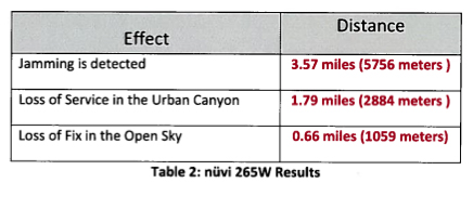
The potential interference is charted here:

Interference to consumer grade GPS receivers

For FAA-certified GPS receivers, the data is worse:

Interference to FAA certified GPS receivers

The FAA-certified aviation receivers are more sensitive, therefore, more likely to be impacted.

It makes me wonder, what is going on in Washington?

UPDATE: March 3, 2011, KNX, Los Angles runs with the story: Planned 4G service could cause widespread GPS jamming

The Nautel ND-5 transmitter

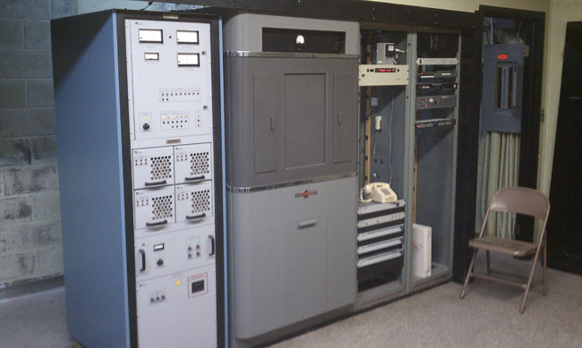
This transmitter is about 10 years old. In ten years of service, there have been no failures.  Not one transistor has gone bad.  It is connected to a three-tower directional array on 920 KHz.

WGHQ Nautel ND-5 transmitter

Sadly, this model transmitter is no longer made.  They were built like tanks, heavy gauge steel cabinets, well-designed, well-grounded circuit boards.

It is dirt simple; RF power MOSFETs on drawers, combined and tuned with the output network.  A power supply, exciter, and simple control logic and nothing else.  No serial port to plug a computer into, no ethernet ports, no digital read-outs, fancy efficiency optimizing computers, etc.  In the meantime, it does what it is supposed to do, stay on the air.

I was reading, with interest, the idea of “energy star” transmitters.  I think that good radio station engineers already take electrical efficiency into account when buying a new transmitter.   That being said, electrical efficiency is not the only measure of efficiency an engineer should be considering.  Reliability, redundancy, and repairability must also be considered.  If the station spends an inordinate amount of time on the old backup transmitter while the new, super-efficient main transmitter is off line is counterproductive.  Not to mention the time wasted troubleshooting which could be better spent on something else.

TIA/EIA 568

Radio stations more and more revolve around networked computers.  Engineers need to understand computer networking, especially as it relates to audio distribution and playback.  Eventually, I see broadcast engineers being more computer science types rather than electrical engineering majors.

What I have found out about computer networking is this: it is not rocket science.  In fact, most of it is pretty easy.  Physical networking and cabling are similar to audio and TELOC cabling.  Automation computer servers themselves are not difficult to understand as most of them run on some type of Windows program.  Other servers such as Apache for WWW and for FTP and streaming run on some type of LINUX OS.  LINUX is also not difficult to understand so long as one knows the right command line prompts.

The first part of understanding computers is networking.  Without a computer network, a computer is a glorified typewriter.  Almost every automation system and or digital editor requires some type of network.  Consoles and computers that use AOIP require well-constructed networks in order to operate properly.  To that end; cabling choices, network interface devices such as switches and routers, patch panels, and so forth need to be specified and installed with care.

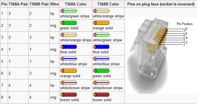
Most often, it is the simple things that will trip an installer up.  The one area where I have found the most mistakes made is the pair’s connection to various termination points.  There are two basic standards, TIA/EIA T568A and T568B.  Neither is better than the other, both are often identified on terminating devices such as jacks and patch panels.  The most important aspect of these standards for an installer is to pick one and stick with it.

TIA/EIA 568 color code

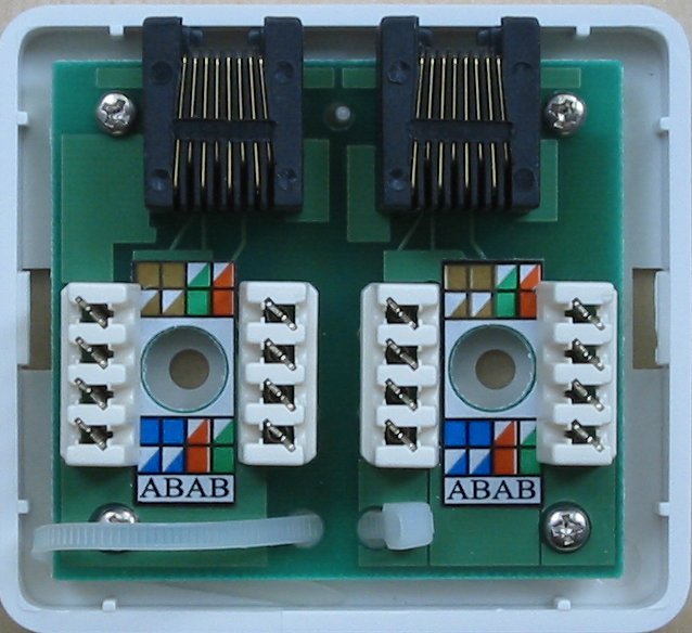
When certifying networks, the most common problem I have encountered is crossed pairs.  Almost invariably, one end will be punched down with the A standard and the other with the B standard.  Jacks are particularly difficult, as the color-coding stickers show both.  Many patch panels have a slide-out, reversible card with is an either/or situation.  For some reason, I have stuck with the B standard, and on any project I am managing, I get rid of all the A color codes I can find and tell the installers that B is the only acceptable termination standard.  That cuts down on a lot of errors and redos during certification.  That is good, it saves time and I hate redos.

Cat 5e wall jack set

You can see that this color code marking can lead to confusion.  I take a sharpie and cross out all the A markings to avoid installation mistakes.

Incidentally, on any new network installation, Category 6 cable should be used.  As more and more data throughput is required for network applications,  Category 6 Cabling has better performance specs and will likely have a longer service life than another cable.   It may be a little bit more expensive than Cat 5,  however, well worth the investment.  It would be a great mistake and a waste of money to have to pull out the network and reinstall it in a few years because the cabling doesn’t have the required bandwidth.

Category 7 cabling is in the works.