This was in the back room of one of the radio stations we work for:
ERI LPX2E FM antenna with RADOMES on the ground
It is a burned-out ERI LPX2E antenna. The manager was complaining that it took up too much space and he didn’t know what to do with it. Could I get rid of it? Sure, no problem. I could at least cut it up and scrap it.
When I first looked at it, it seemed complete and undamaged, however, upon further examination it seemed that some of the inter-bay line had overheated and one of the tuning sections that goes from the power divider out to the bay was missing. Therefore, I took it apart and separated the copper from the brass. Most of the antenna is made from yellow brass, due to its hardness. The inner line sections are copper and the mounting hardware is all stainless steel. I will perhaps break even time-wise, but it is one of those projects that can be done on my time in between other paid work, so it will be fine.
ERI rototiller antenna bay
I am going to keep one bay intact with the RADOMES on as some sort of modern art project. My daughter thinks we should install it in the yard as a part of a fountain-fish pond-bird bath contraption. The idea is to mount the bay facing up as in the picture above and run a hose up the inside of the transmission line to the T section. A hole will be drilled there and some type of fountain head installed to spray water up over the RADOME. The system will be run by a solar-powered pond pump. I’ll have to take pictures when it is done.
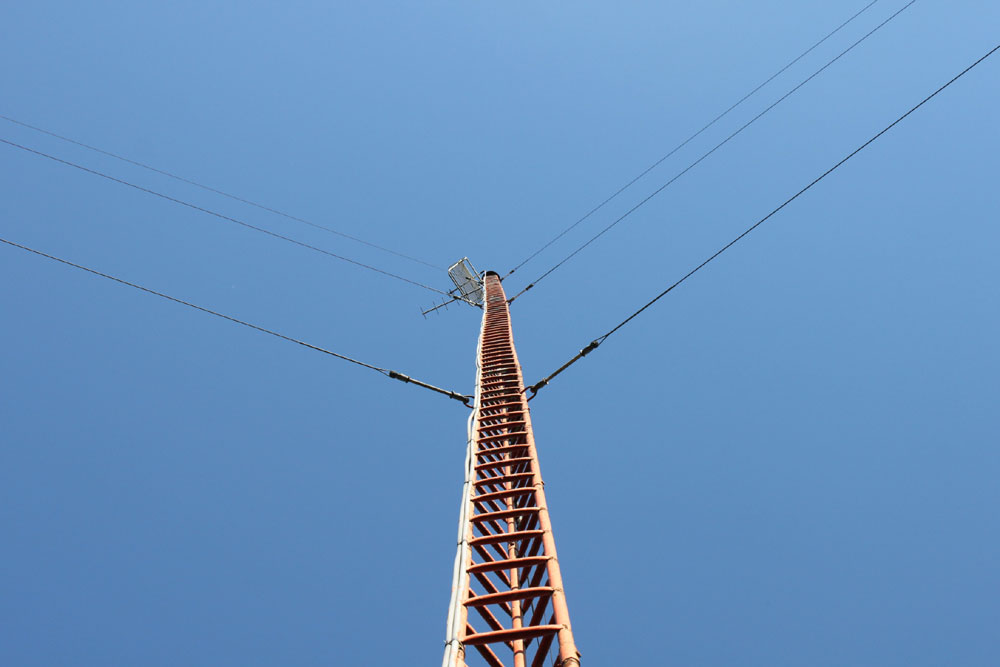
This is a situation that is and will be playing out over and over throughout the country as the decay advances. W*** signed on the air in March 1963. I believe this is the original tower:
W*** tower
As you can clearly see from this picture, this tower has several problems. Aside from the loose guy wires, the rust, and general structural decay, it is bent in several places. Currently, the forces are in equilibrium, but for how long, no one knows. It is certainly not safe to climb. At 144 feet, it is no longer required to be marked or lit, thus, over the years, the paint peeled, the weep holes filed up, and the guy wires rusted and loosened, which leaves us with the situation today.
At the transmitter building, there are other issues with the basement flooding, mold, etc. Truth be told, this station makes no money on its own. It would cost several tens of thousands of dollars to fix all these issues, and for what; a high end of the broadcast band class D AM station which has not shown up in the ratings for fifteen years. Once upon a time, it was a surviving, perhaps not thriving, local radio station. Those times have long since passed.
The question is; what to do with it? Sign it off and surrender the license? Fix all the problems and continue to broadcast? Donate it? If so, who would take it? Or, more likely, wait until the tower collapses and deal with it then.
I’d imagine that there are many others just like it dotting the country. On the whole, the AM broadcasters that are viable would be better off if this dead wood was cut away and discarded.
Since the FCC waved some of its rules regarding carrier power and carrier shift on the AM broadcast band, AM stations are now able to implement MCDL or DCC (Dynamic Carrier Control) technology to save money on their electric bills. This technology has the potential to save tens of thousands of dollars for higher-powered AM stations (high power=greater than 10 KW carrier level).
On a standard AM broadcasting station, the carrier represents two-thirds of the energy being transmitted, with the modulation index containing the other one-third. The carrier contains no information; it is simply there on the center frequency at the power level authorized by the station’s license. Thus, if the carrier can be reduced without affecting the quality of the broadcast reception, it will reduce to the overall power consumption of the transmitter. In areas where electric costs are high, the savings can be substantial.
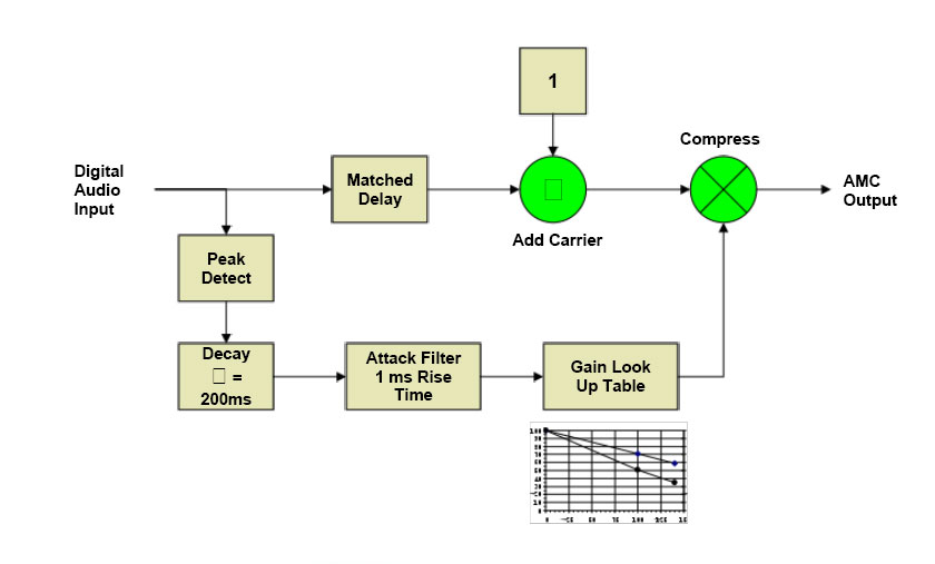
There are various ways to accomplish this. The first is called Dynamic Carrier Control (DCC), where the carrier voltage is reduced during moderate modulation levels (between 20-50%) and restored during peaks. This reduces the output power during average modulation, restoring most of it during quiet periods and peaks. The next is Dynamic Amplitude Modulation (DAM), which is similar to DCC. The most savings will be noted with less heavily processed programming such as talk radio because the higher the average modulation density is, the less the MDCL circuit reduces the carrier voltage level. The little graph in the diagram shows the reduction in the carrier voltage vs. modulation levels.
Nautel DAM block diagram, courtesy of Nautel, Ltd.
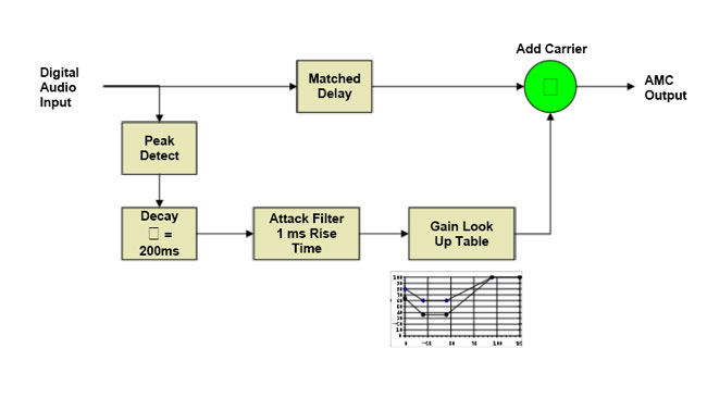
Finally, Amplitude Modulation Companding (AMC) reduces the voltage in both the carrier and modulation product during peaks. This results in better savings for higher-density modulation indexes. It is also the most transparent of the three schemes, as the carrier is restored to full power during periods of low or no modulation levels. During peak modulation, the reduction does not drop the power level below the un-modulated carrier level. The little graph in the diagram shows the reduction in the carrier voltage vs. modulation levels.
Nautel AMC block diagram, courtesy of Nautel, Ltd
Nautel has done extensive work on MDCL and includes several algorithms in their NX series transmitters. For older Nautel transmitter models such as ND, XL, XR, and the J-1000, there is an outboard exciter, which is in a one-rack unit chassis. Older transmitters may need a simple field modification to create a DC-coupled audio input. The cost for the upgrade is approximately $5,000 USD, however, check with the regional Nautel sales rep.
Once the system has been installed, there are several things to be aware of:
Modulation monitors may not work properly, especially older units, which will show significant carrier shifts and have carrier alarms. Belar AMMA-2 modulation monitor is specifically built to work with MDCL transmitters.
When making field strength readings, the MDCL circuitry must be turned off to get accurate readings.
For stations running IBOC, the amount of carrier power reduction may need to be experimented with, as the effect of the carrier reduction may cause the transmitter to exceed the NRSC mask.
Currently, only Nautel and Harris are selling MDCL transmitters. I spent several minutes poking around the Harris website and looking through their product brochures for the DX series transmitters and no mention of DCC o MDCL was found. I’d be happy to include any information from Harris if it were made available.
I found this on one of the guy wire anchor points for a 400-foot tower:
#2 solid copper wire burned open by a lightning strike
Had to be a pretty big hit to burn open a #2 wire. This is on one of six guy anchor points for the tower. The ground wire is U-bolted to each guy wire before the turnbuckle and then goes to ground. This was noted between the last guy wire and the ground rod.
It is important to find and fix these things, as the next lightning strike on this tower would have a less-than-ideal path to ground at the guy anchor points, forcing the current to flow through other parts of the transmitter site, possibly through the transmitter itself, to ground.
I generally try to do a brief inspection of towers, guy anchors, lighting, painting, and a general walk around the property twice a year. That helps prevent surprises like “Oh my goodness, the guy wires are rusting through,” or “Hey, did you know there is an illegal “hemp” farm on your property?” Well, no officer, I don’t know anything about that…