This year, winter in the Northeast has been relatively tame (so far). As I type this today, the temperature is 60 degrees F. The average high temperature this time of the year is around 40 F. This is an anomaly due to the strong El Nino currently going on in the Pacific Ocean. Next year will likely be closer to normal.
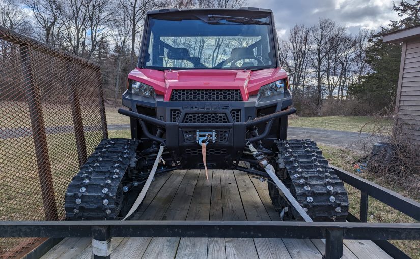
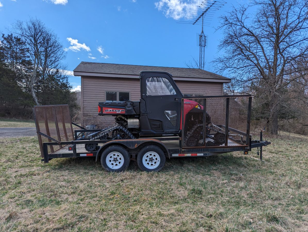
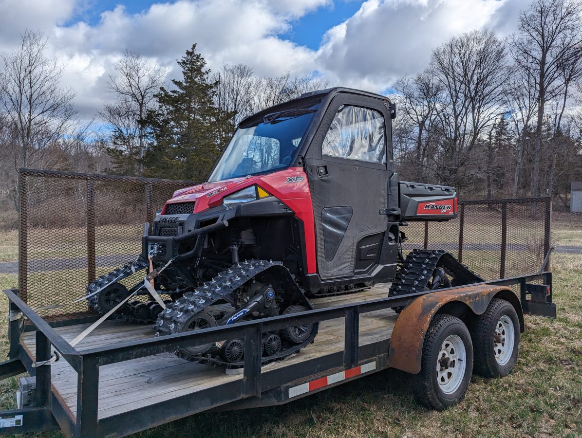
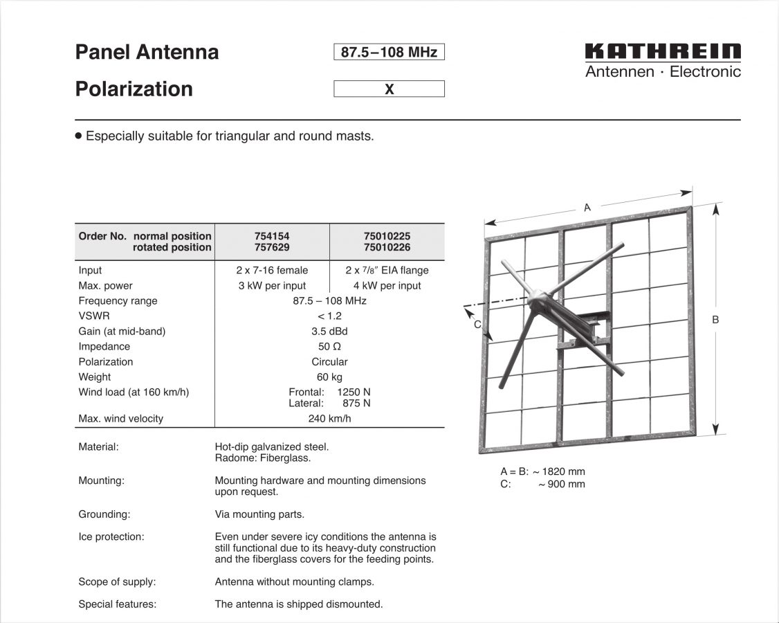
To that end, one of the problems in winter time is access to mountaintop transmitter sites. Several of the sites we maintain can only be accessed with special equipment such as a snowcat, track machine, or snowmobile. We have two or three sites that are cut off from regular vehicular access for 2-4 months per year. One site in particular has water flowing down the access road from a reservoir creating a 200-foot sheet of ice that is not even walkable.
For many years, I have been on the lookout for some special equipment that will allow us to get there safely and back.
Meet the special equipment:
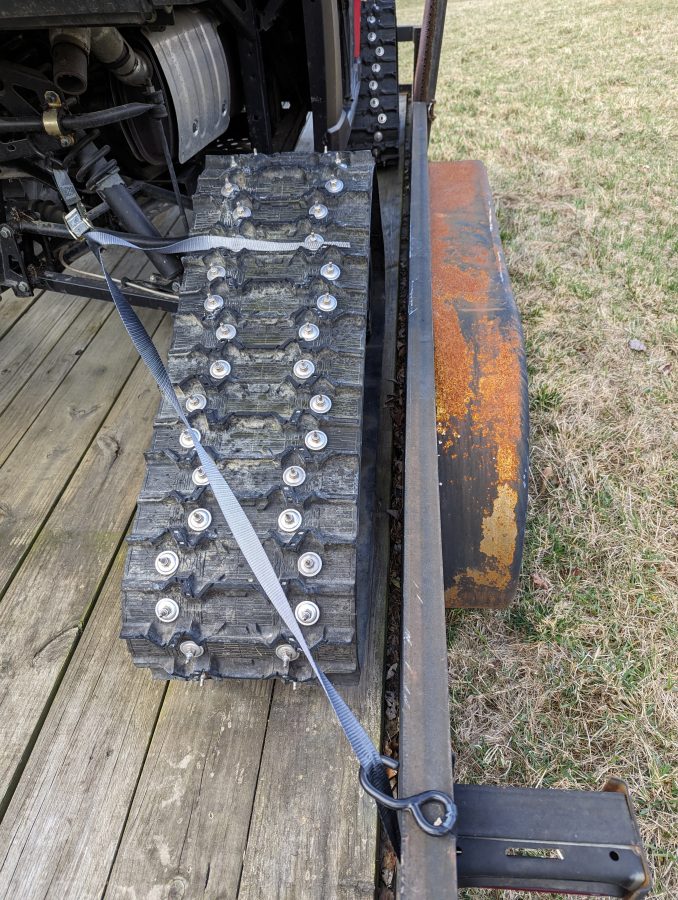
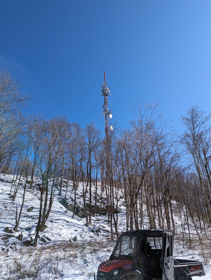
Polaris Ranger 900 with studded tracksThe wheels were replaced with tracks and we added this stud kit for icePolaris Ranger 900
Like other such items, there is a cost associated with owning this. In the past, we have paid a two-way radio company that has a larger snow machine for rides to the top of various mountains. That can get pricey if several trips are needed. We will have to figure out a reasonable fuel surcharge for the operation of this track machine.
One of our clients needs to move to another transmitter site because their lease is expiring at the old site. We have been working on this for several months now. One of the nice features of this project is the panel antenna.
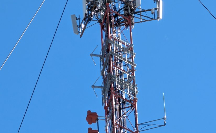
Kathrein 754154 spec sheet
This is installed in a 2-bay 3-around configuration. I don’t see this particular model in the Kathrein catalog anymore, but there are other cross-polarized panel antennas available from them.
Colocated tower
There are many existing services on this tower including two full-power FM stations, a translator, a VHF TV station, numerous cell carriers, etc. Once the installation is done we will have to check carefully for intermodulation.
Honda Track Machine
Winter in the Northeast; there was just enough snow and slush on the access road that the truck could not make it to the top of the hill. This track machine works great. We have added a Polaris Ranger 900 to our inventory (not this machine) for winter access to several of the more difficult transmitter sites. While I do enjoy the occasional walk in the snow, the key word here is occasional.
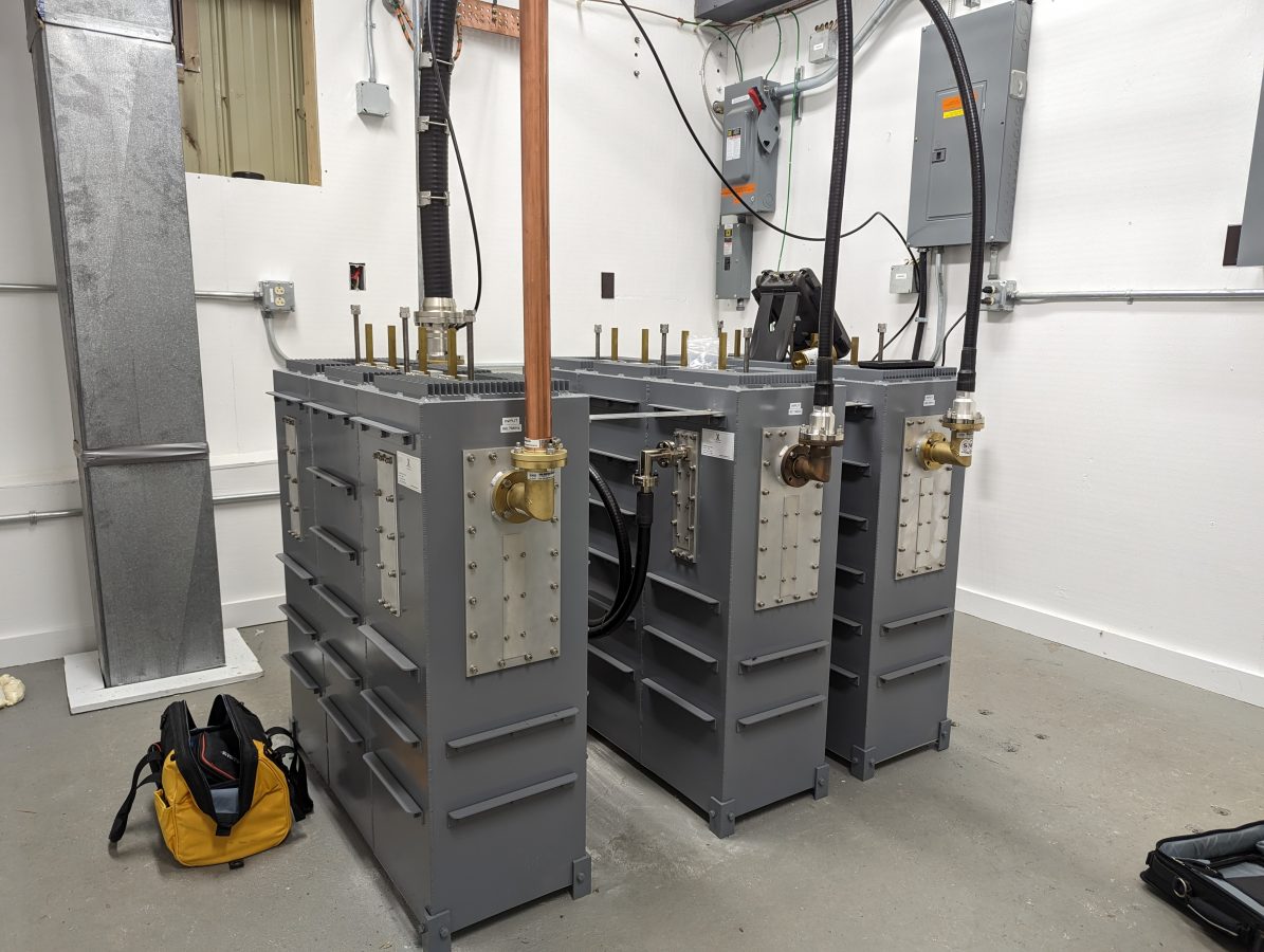
AAT branch combiner inputs
The three stations are combined into the panel antenna with this rather nice American Amplifier Technologies C-IR-3-3-30K-N branch combiner.
AAT branch combiner output side
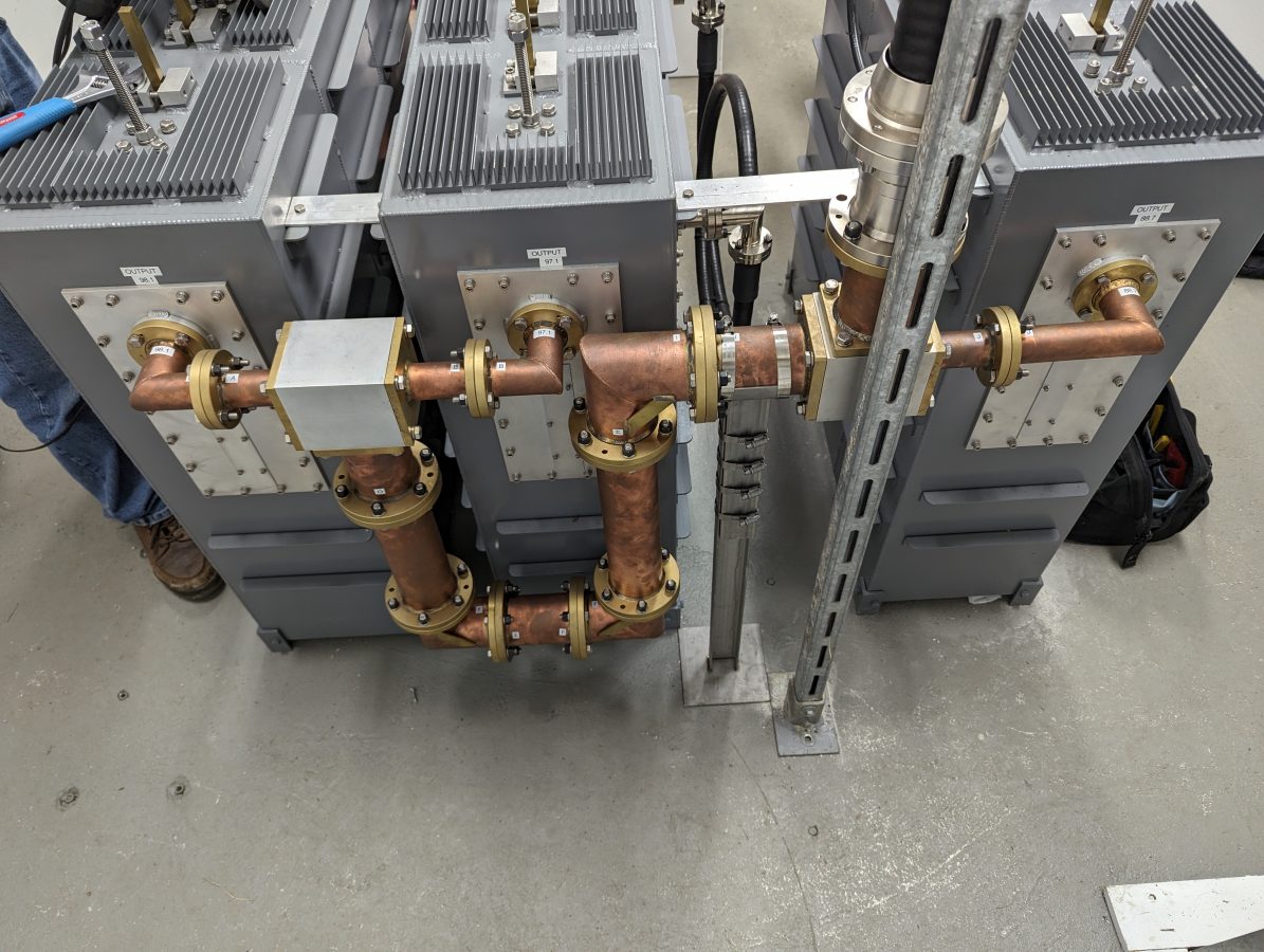
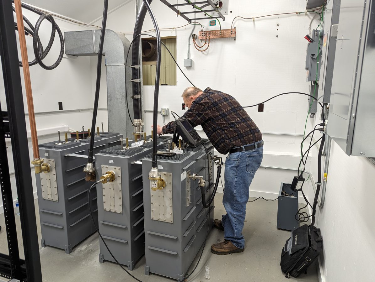
The input filters needed a slight adjustment to compensate for the difference between the test load they were tuned to and the actual antenna load they will be running into
Touching up input filters
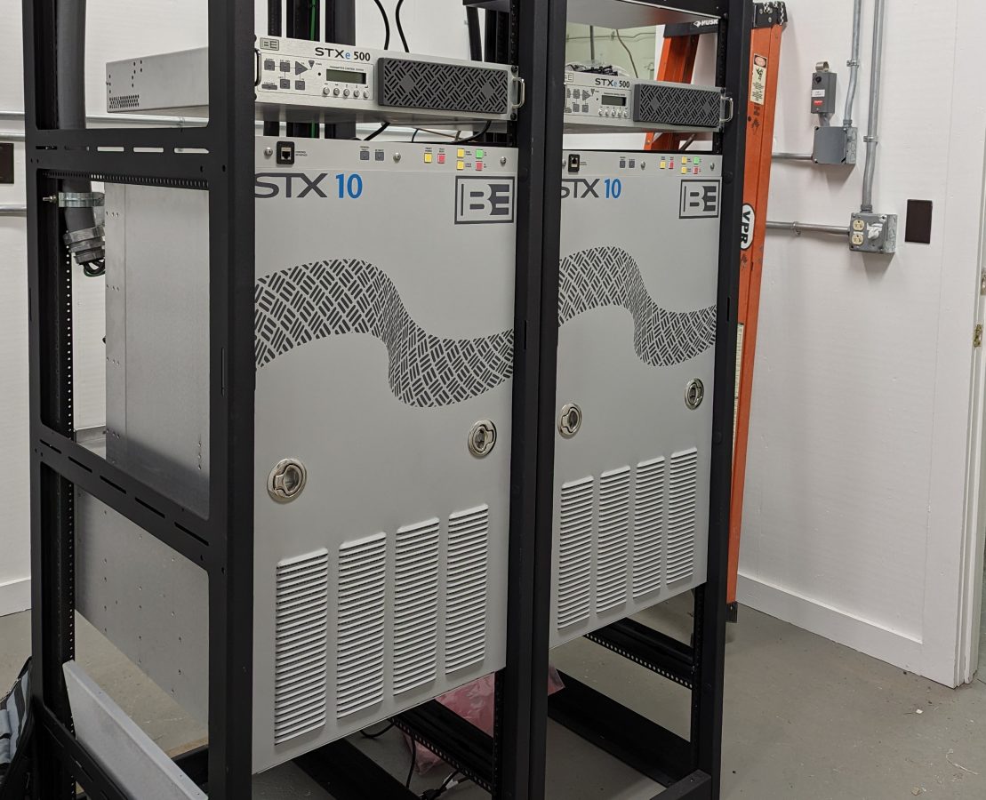
Two of the transmitters are Broadcast Electronics STX-10 units. We have had good service from the STX-10 which was installed on Mount Beacon a few years ago.
Pair of BE STX-10 transmitters
We are waiting for the Comrex Bric Link III to come back from the factory after their firmware update. They are to be used for the STL. Once they are returned, we should be good to go for site turn-up.
Several companies make variations of this antenna; Scale FM-CL is a lower-power version that is used mostly by translators. They are highly directional and can be installed in a vertical, horizontal, or cross-polarized (45-degree slant) manner. This model input power is 5 KW per bay and the manufacturer’s specification is for 1.28:1 or less VSWR across the entire FM band. In the slant configuration, which Shively states is right-hand circularly polarized, the gain is 4.03 dB.
I recently did some work onsite for WXMD, California, Maryland. They were having some issues with high reflected power readings on their transmitter and suspected an antenna or transmission line problem. The station has been on the air for about 10 years and began having issues late last year after a thunderstorm passed through the area.
WXMD California, MD South East Bay Shively 6025 antenna
The main issue was that the transmitter was showing 243 watts of reflected power with 9800 watts of forward power, while the inline watt meter showed 37 watts. As part of the repairs, a new 1 5/8 transmission line was run up the tower replacing the old line which was damaged at the power divider input connector. A new power divider was also installed. Was the antenna still defective? Was the new transmission line and/or power divider defective? Was there an issue with the inline watt meter? Questions, questions, questions…
Thus, several sweeps were needed to verify things:
1 5/8 inch line terminated at the power divider with known good load
This antenna has a power divider that splits the power between a southeast-facing antenna bay and a southwest-facing antenna bay. To be sure that we were not dealing with a bad connector or transmission line, the line was swept in isolation from the input of the inline watt meter to the input of the power divider. This showed that the transmission line, connectors, elbows, and inline watt meter were all good.
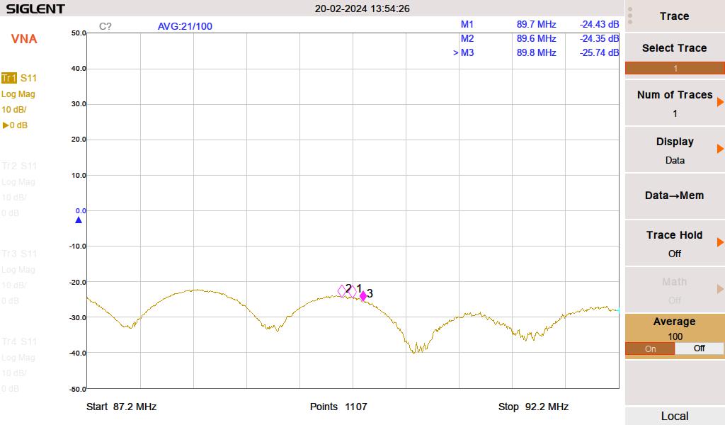
Southeast Antenna SWRSoutheast antenna return loss
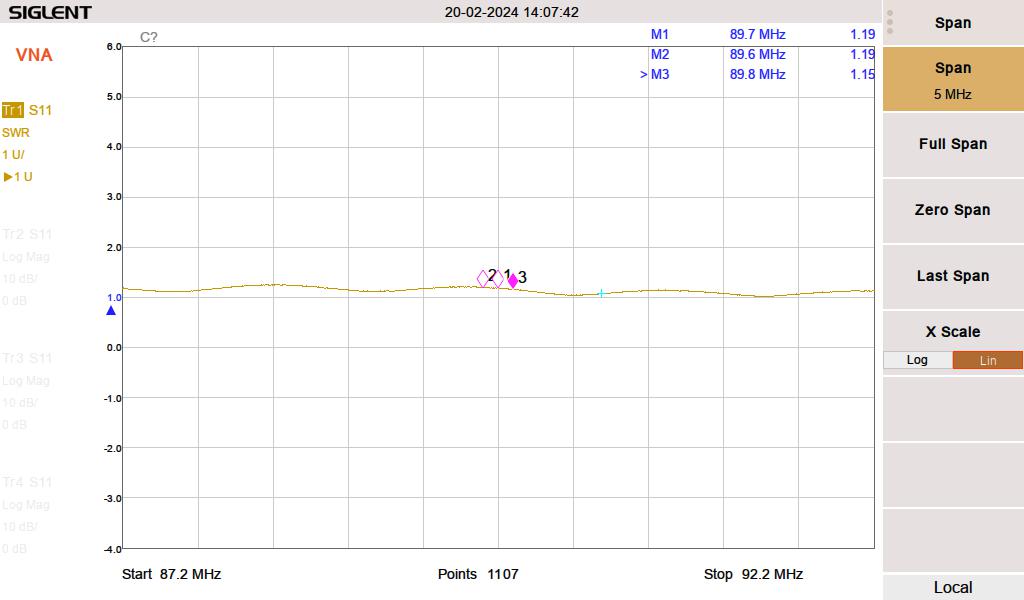
Next, each antenna bay was swept individually. The power divider port going to the disconnected antenna was terminated with a known good 50-ohm load.
Southwest antenna SWRSouthwest antenna return loss
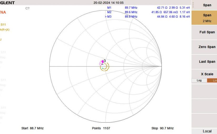
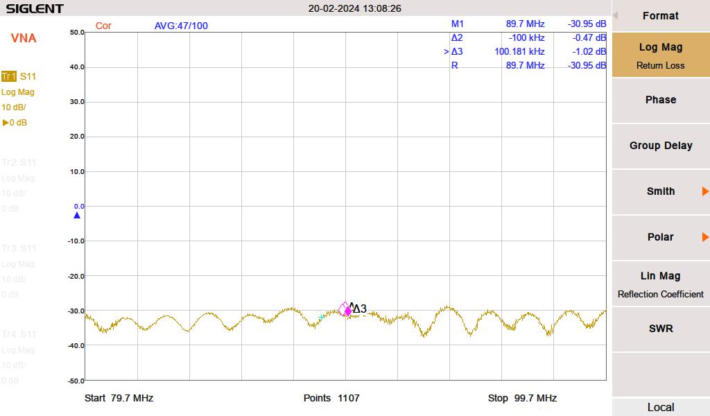
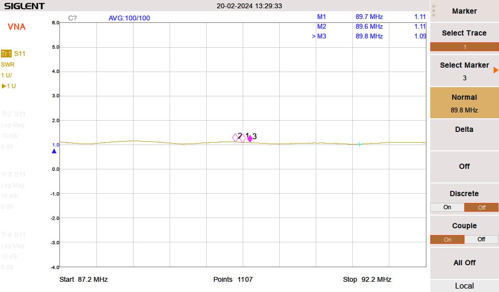
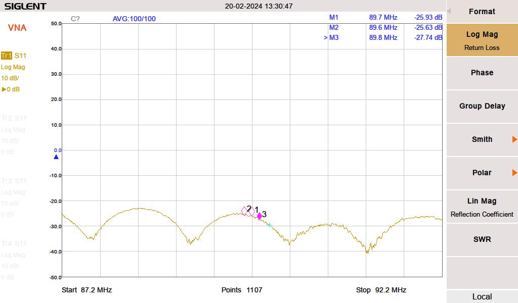
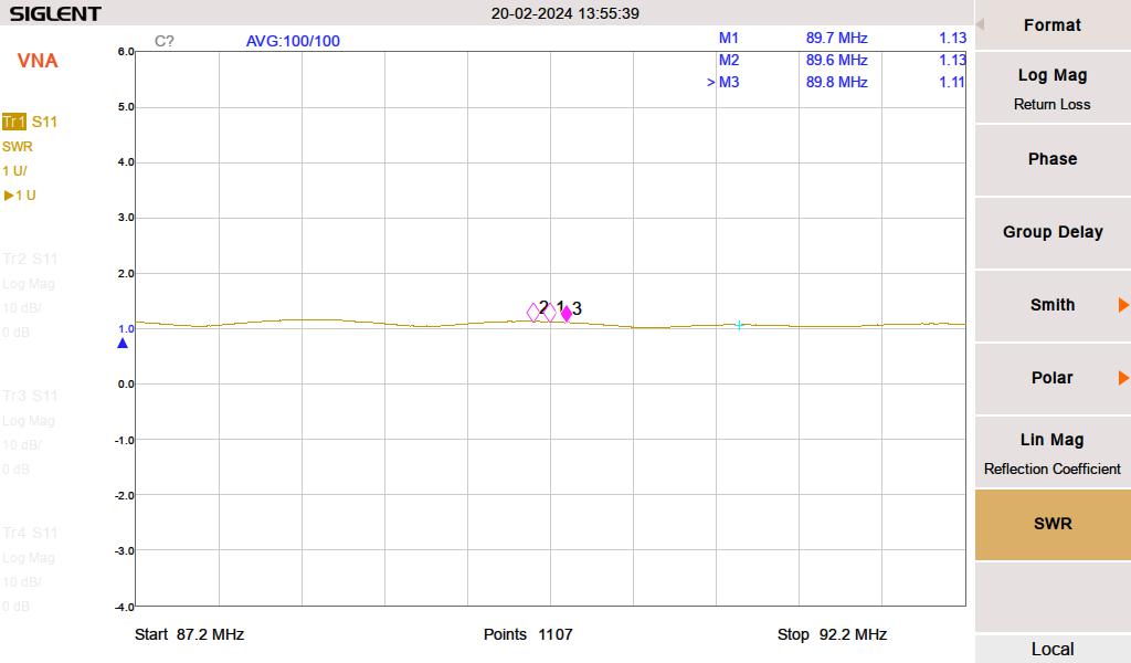
Once the individual bays, jumpers, and power divider tested good, the entire antenna system was swept.
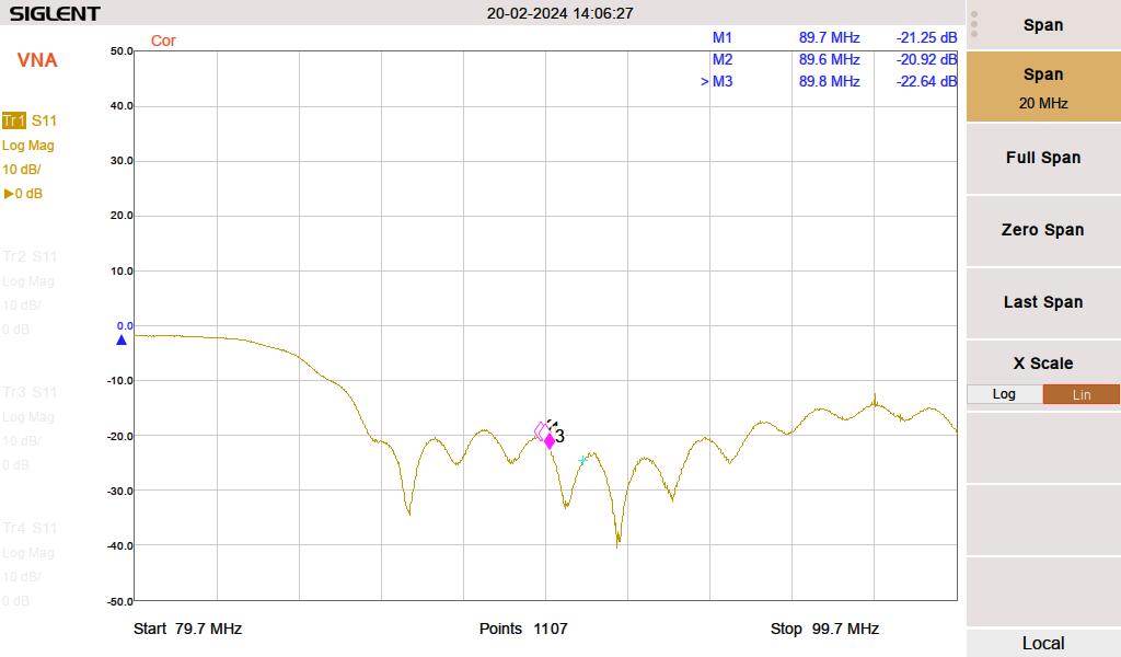
Full antenna SWR
With everything connected, the SWR showed 1.19:1. Not ideal but not terrible either. The inline watt meter readings were verified with a precision watt meter and the final SWR calculated by hand was 1.16:1.
Full antenna return loss
Therefore, the antenna system is performing within the manufacturer’s specifications.
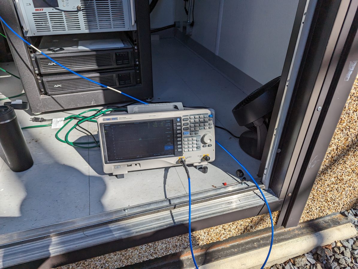
Network analyzer
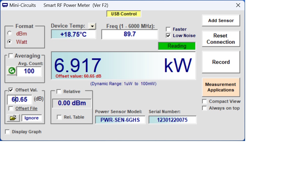
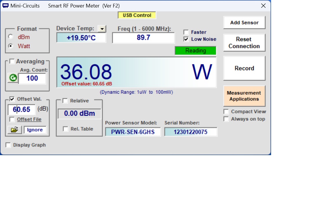
The American Amplifier Technology inline FM watt meter was then checked with a precision power meter. The readings on that device were more or less in line with the precision power meter, thus the transmitter directional coupler is out of calibration.
Mini-Circuits Precision Power meter, Forward PowerMini-Circuits Precision Power meter, Reflected Power
The transmitter shelter is just large enough for one rack. Thankfully, the weather was cooperative, we were able to work outside. Overall, it was a productive trip and an enjoyable experience.
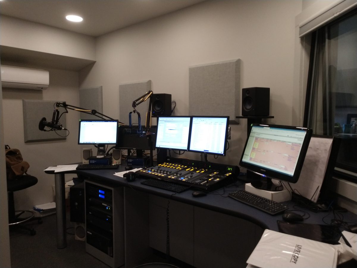
I receive several emails a week from interested readers. One noted that the blog seems to be focused on RF. Yes, that is what I do most, but the company does studio installs as well.
This was from a few years ago.
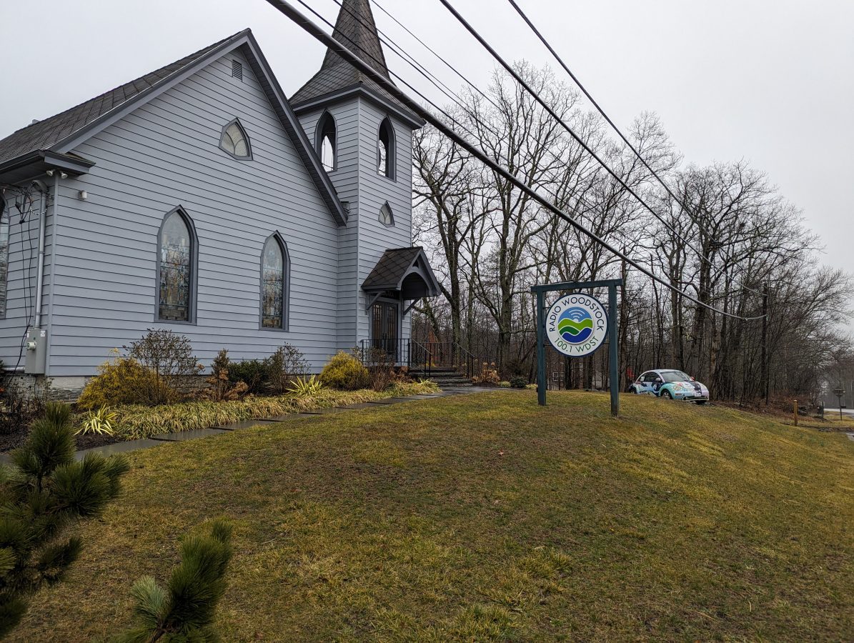
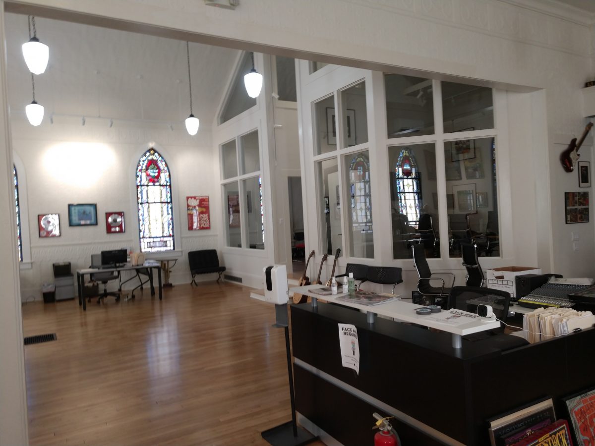
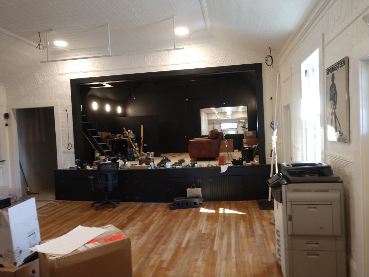
WDST moved out of their Bearsville studio location into the former Methodist Church in West Hurley.
WDST Studios, West Hurley, New York
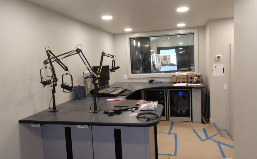
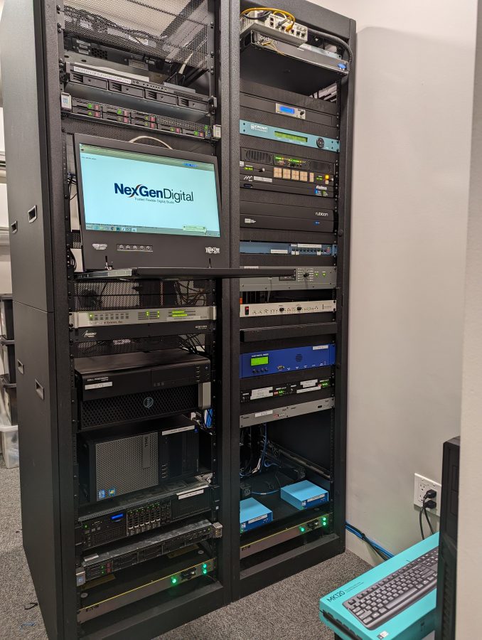
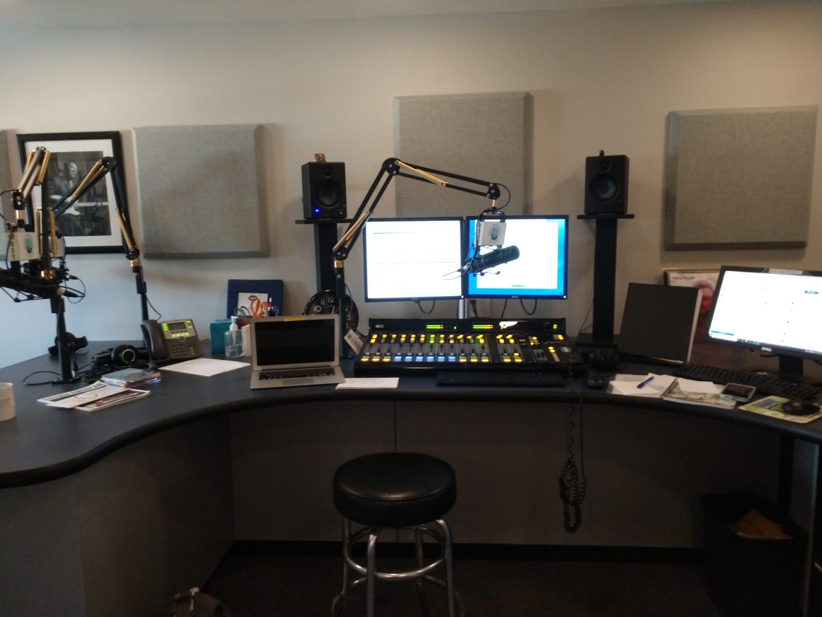
We installed a new SAS audio router and console system.
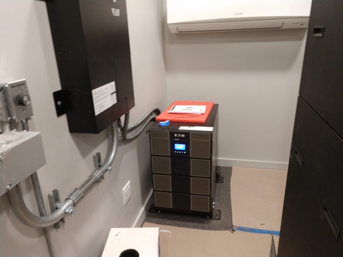
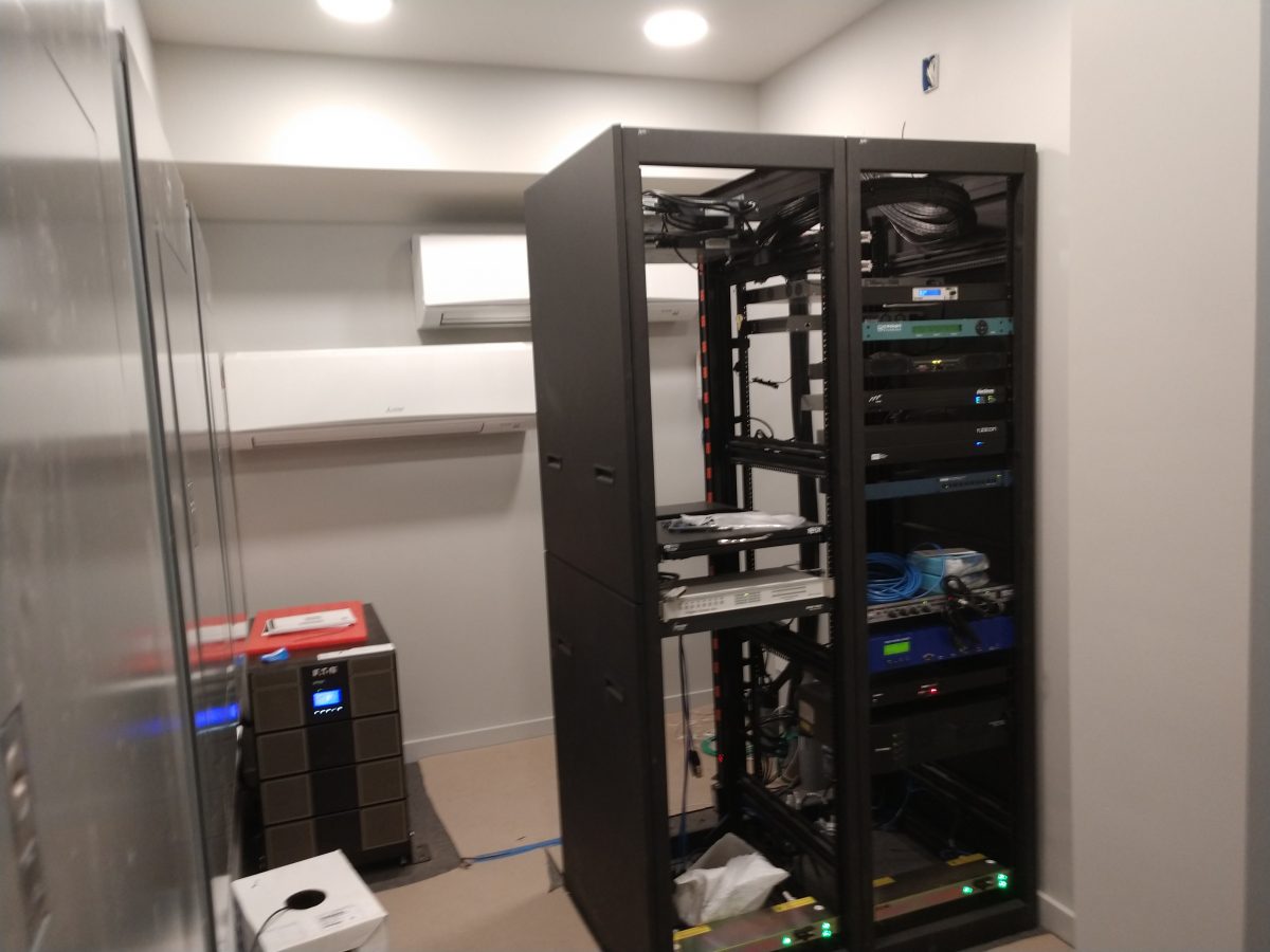
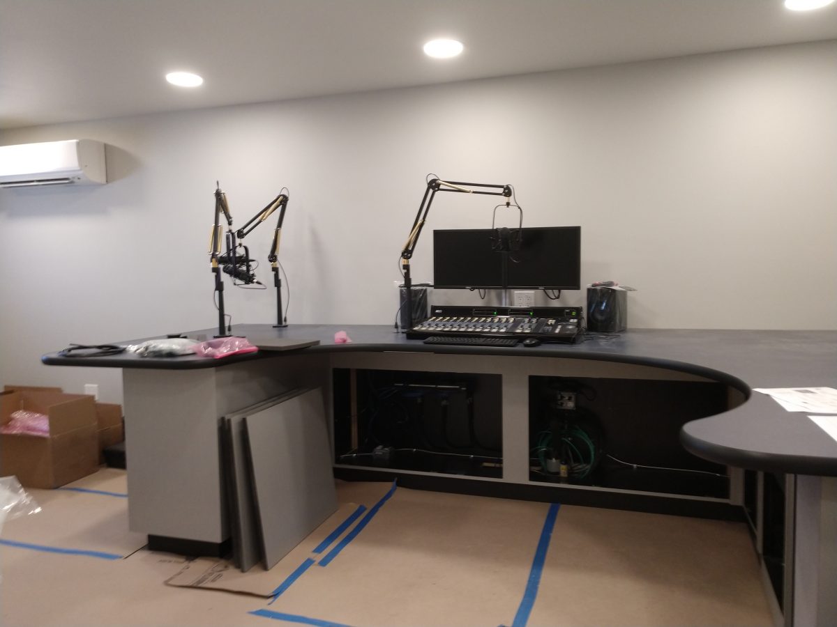
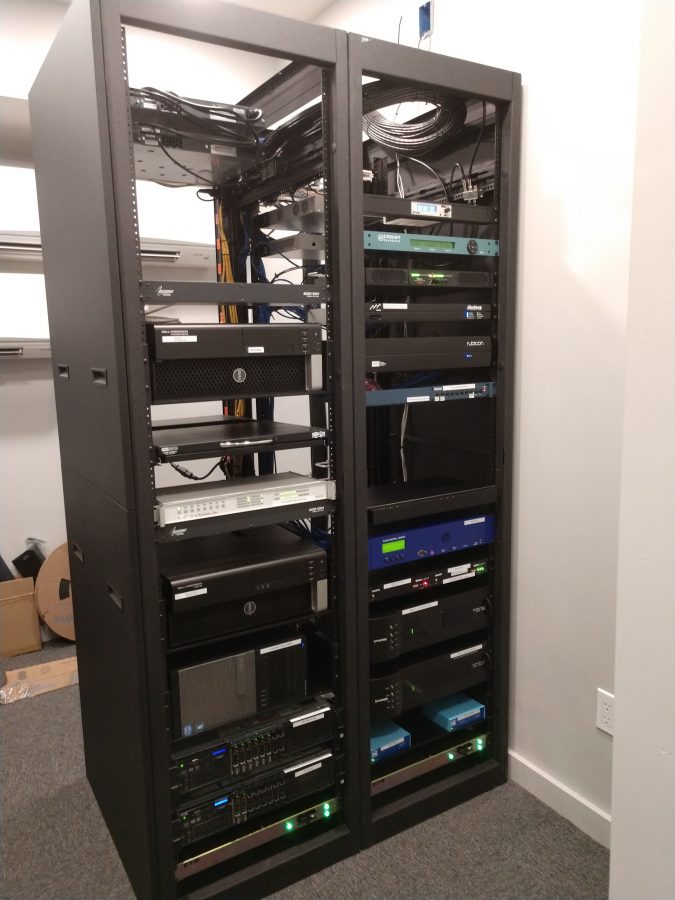
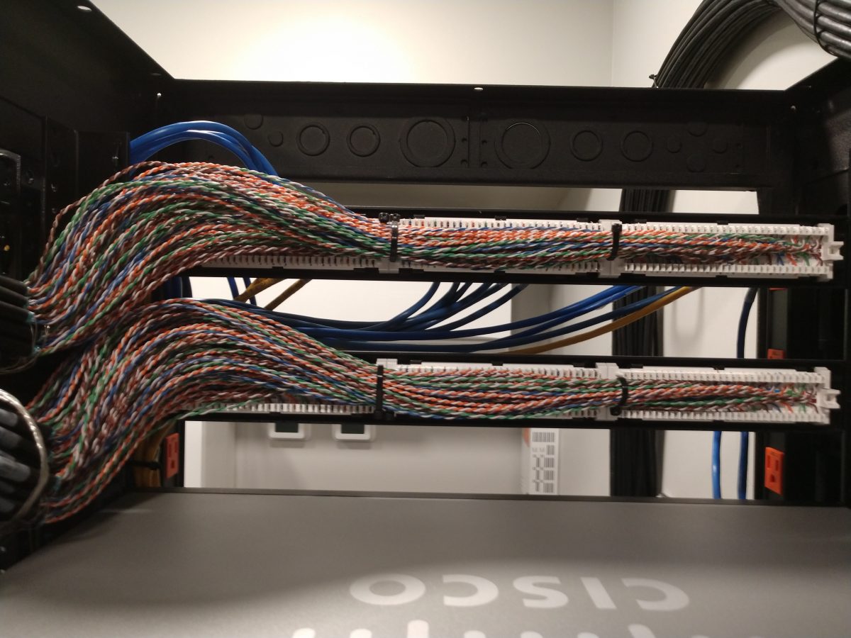
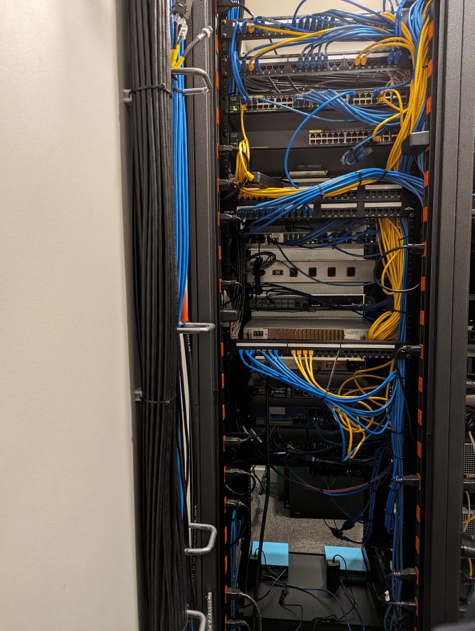
Eaton UPS powers rack room and studiosSmall Rack Room for NextGen servers and STL equipmentAir Studio, Under ConstructionRack RoomEthernet Patch PanelOffice areaLive Performance StageRack RoomBack of the racksWDST Air StudioWDST Production Studio
Pictures of their old Bearsville studio can be found here: