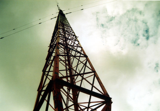
This tower was previously part of a two tower DA. The taller tower was taken down and slowly replaced with a monopole to facilitate vertical real estate development. The shorter tower was retained as the radiator for WKIP-AM, 1,450 kHz, Poughkeepsie, NY.
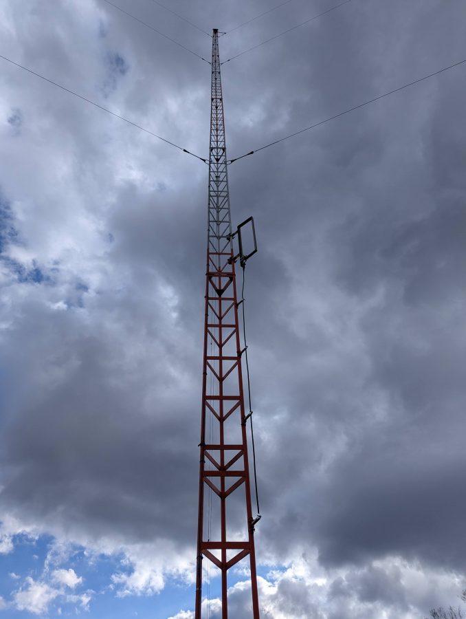
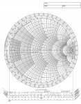
Knowing that the tower is 85 degrees at 1,450,000 Hz, I calculated the height above the base insulator to be 48.816 meters. The tower face is two feet or 0.6096 meters (this becomes important). Using the chart, we can see that the theoretical resistance should be about 25 – 30 ohms:
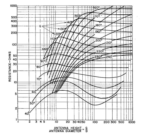
The bottom or X axis on this graph is the ratio of the antenna height over the antenna diameter or 48.816/0.6096 meters or 80.
The reactance is slightly less clear according to this chart:
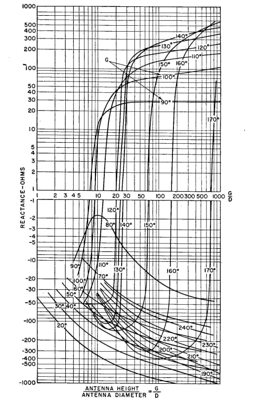
Between 80 and 90 degrees, a large phase shift occurs due to resonance. That means the reactance could be either negative or positive, but will likely be a low number, say +/- 5 ohms. That may be why this height was chosen for the second tower in this system.
And now for a bit of reality; all of that theoretical information is nice, but a measurement under power is where the rubber meets the road. Using the trusty OIB-3, I obtained a reading of 48 ohms base resistance and +j 37.6 reactance. Thus the base current should be 4.56 amps at 1,000 watts.
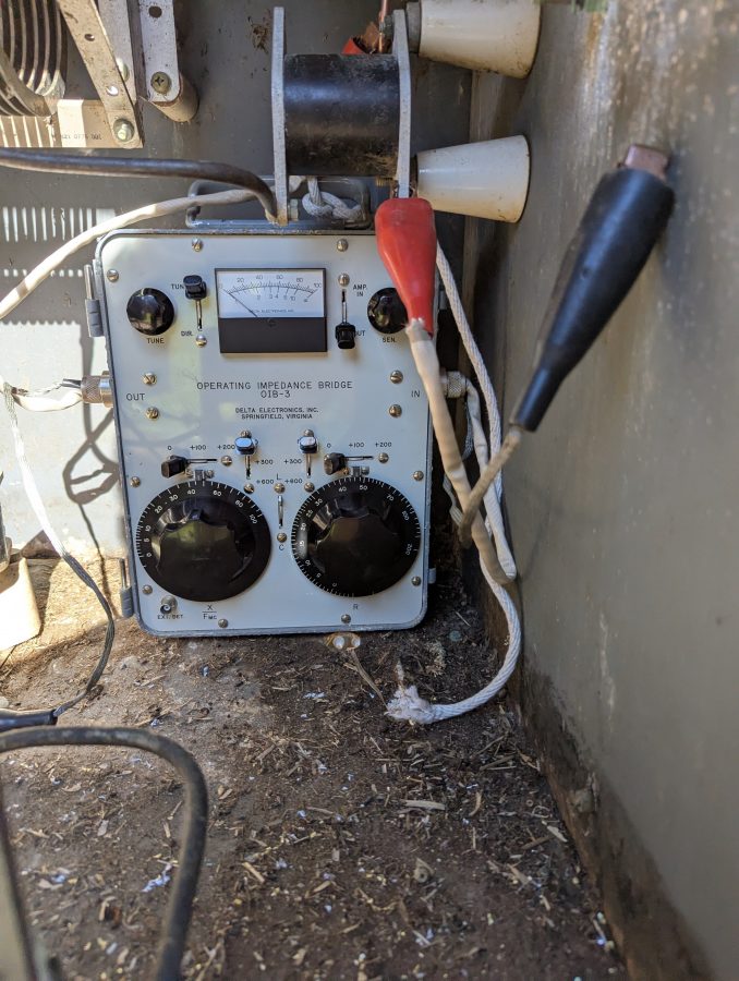
It was a little tricky setting up the OIB-3. The only place for it was far back in the ATU meaning I had to be careful reaching around active components while getting a reading. That being said, it is only 1,000 watts and in the end, no new RF burns were acquired.
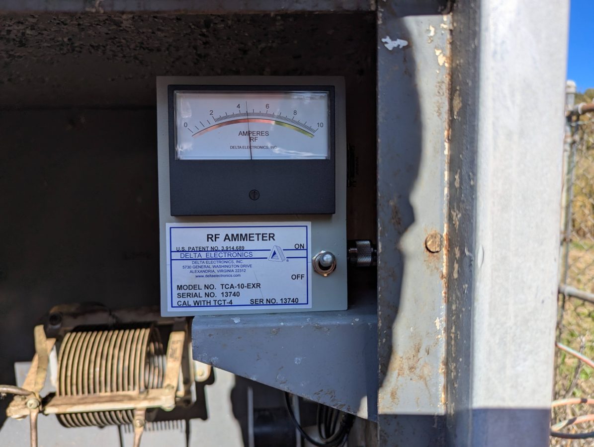
The new Delta Electronics base current meter confirms the measured base resistance with the use of Ohm’s Law; I = √(P/R).
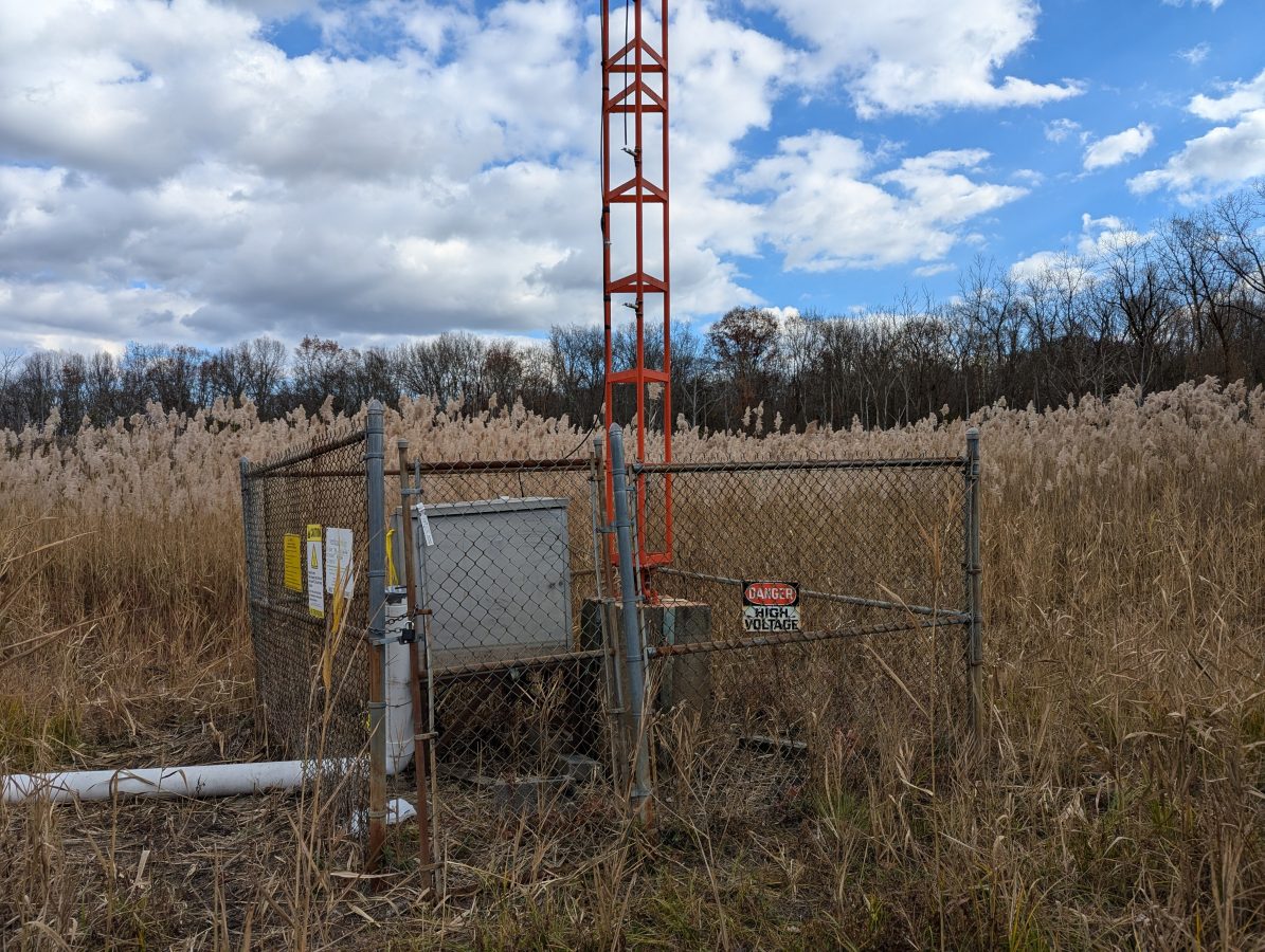
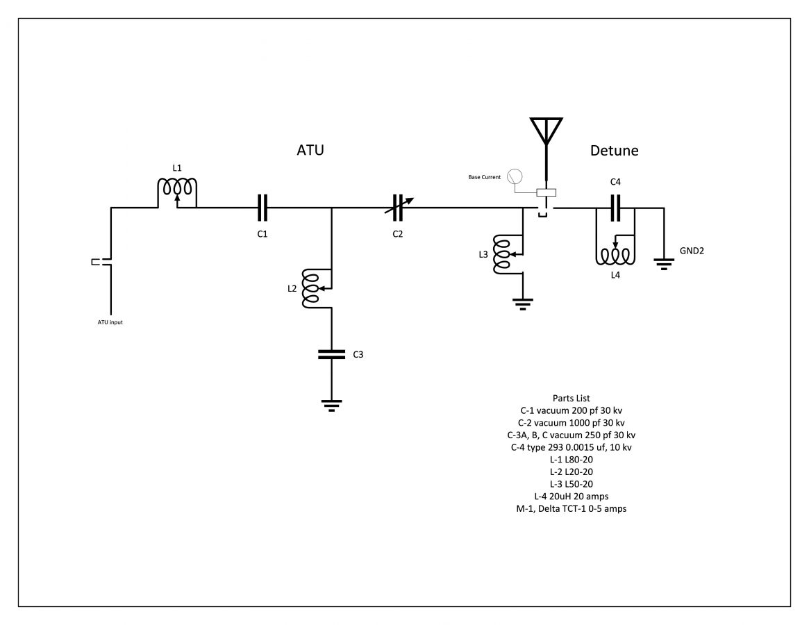
The theoretical information is useful for checking the component ratings in the ATU. The series capacitor on the output leg needs to handle the full carrier current plus 125% modulation. I calculate that to be 10.125 amps, so the 12 amp capacitor is sufficient. In the end, the actual base current was about half of the theoretical, so all good. The ATU is a standard T network with a capacitive leg to ground.
While construction was underway both taking down the old tower and putting up the new monopole, the base impedance of the radiator changed several times. Thus, we waited until all of the construction was completed and the monopole was detuned.
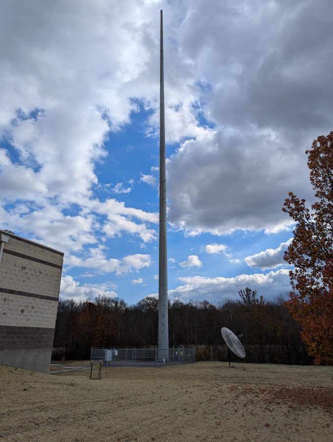
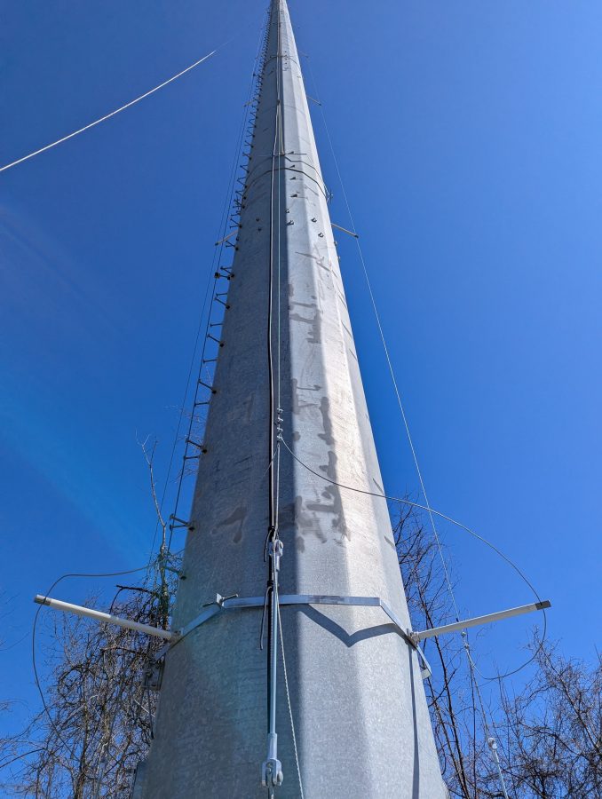
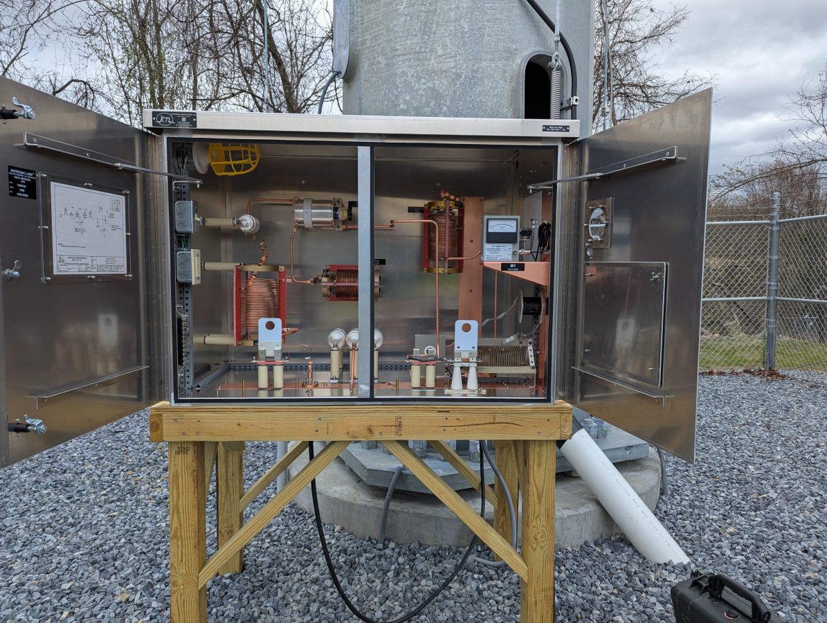
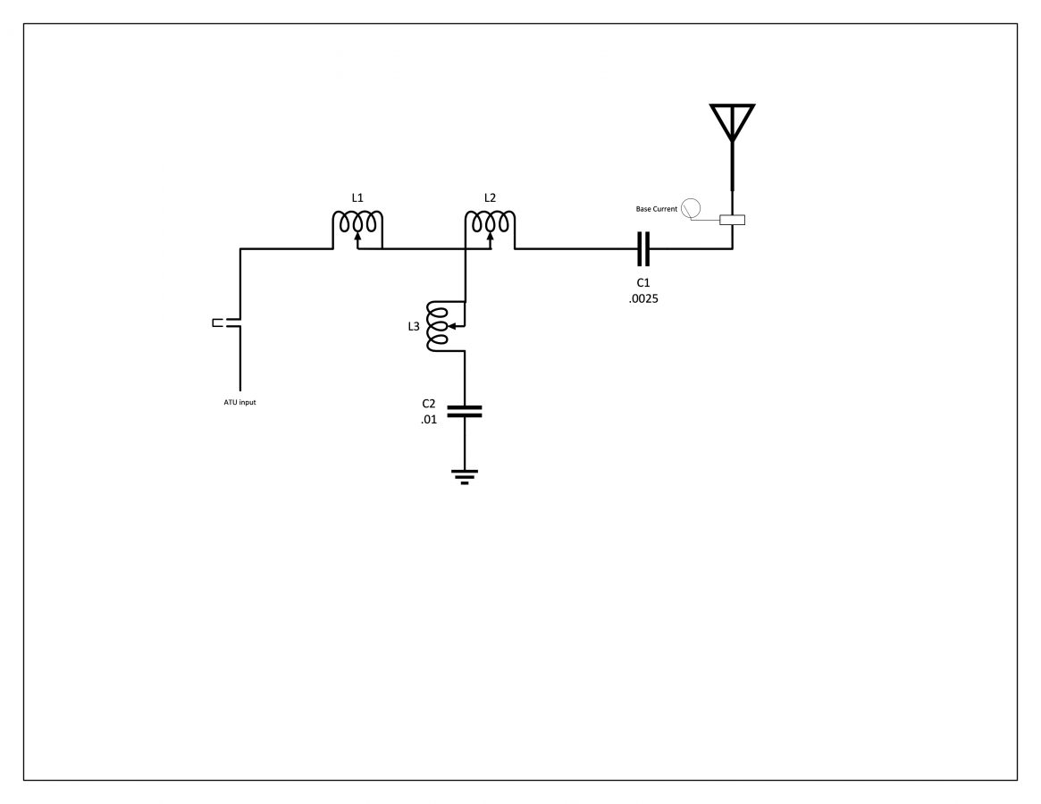
The skirt wires on the monopole are doing double duty. They are first, detuning for the AM tower located about 57 meters (186 feet) away. Next, they are a backup antenna system in case that main tower becomes unusable. This can happen from time to time as the swamp floods or if any type of tower work is needed. To do that I installed another J plug with the detuning network, which will be the normal position. To switch to antenna, it is moved to the antenna position. The base current meter is on the output leg, so it can be used to detune the monopole or measure the station output power.
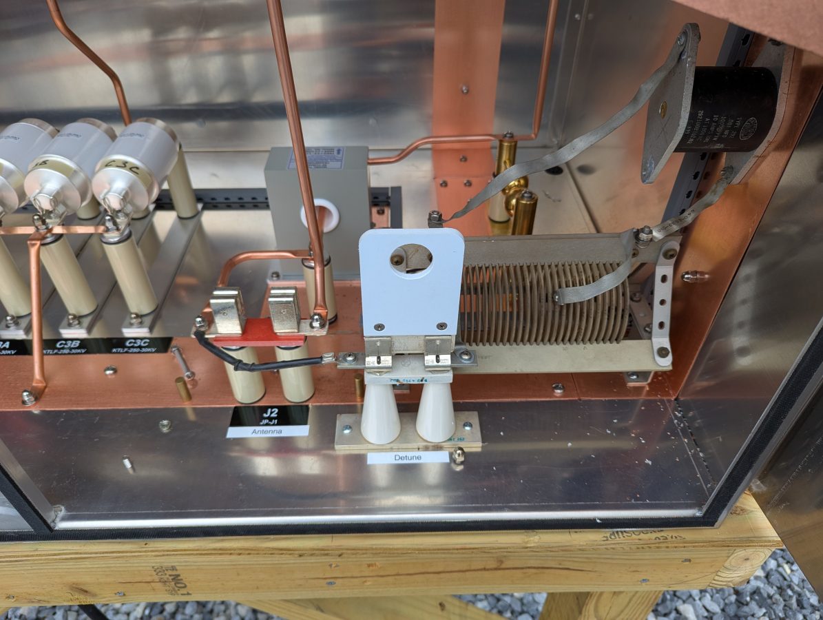
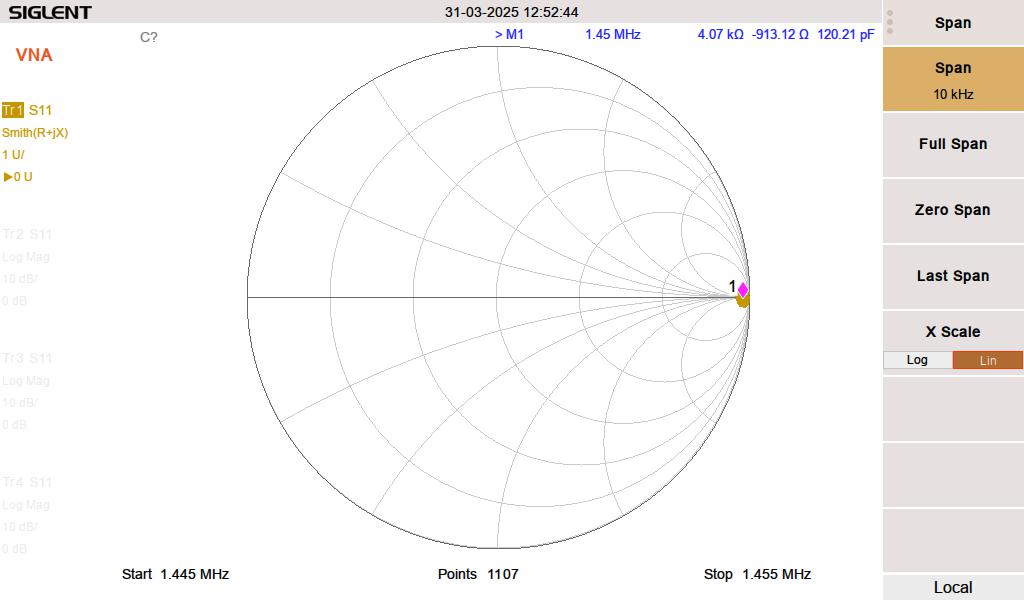
I used the analyzer to get the detuning network close to resonant. The second step involved using the base current meter to touch up the tuning with the transmitter running into the tower 57 meters (186 feet) away. This is necessary because the two structures are close together. The skirt wires on the monopole pick up a lot of RF, therefore the stray capacitance on the inductor coil plays a role in the circuit. The net result is less inductance is needed when the transmitter is on. The resonance point will shift somewhat with ground conditions, but as long as the monopole impedance is high (above say 2K ohms) the structure should be invisible to the nearby 1,450 KHz radiator.
The ATU for the monopole looks like this:
The operating impedance measurement shows a 47 ohm impedance, making the daytime base current 4.61 amps. It is coincidental that the two tower impedances are that close.
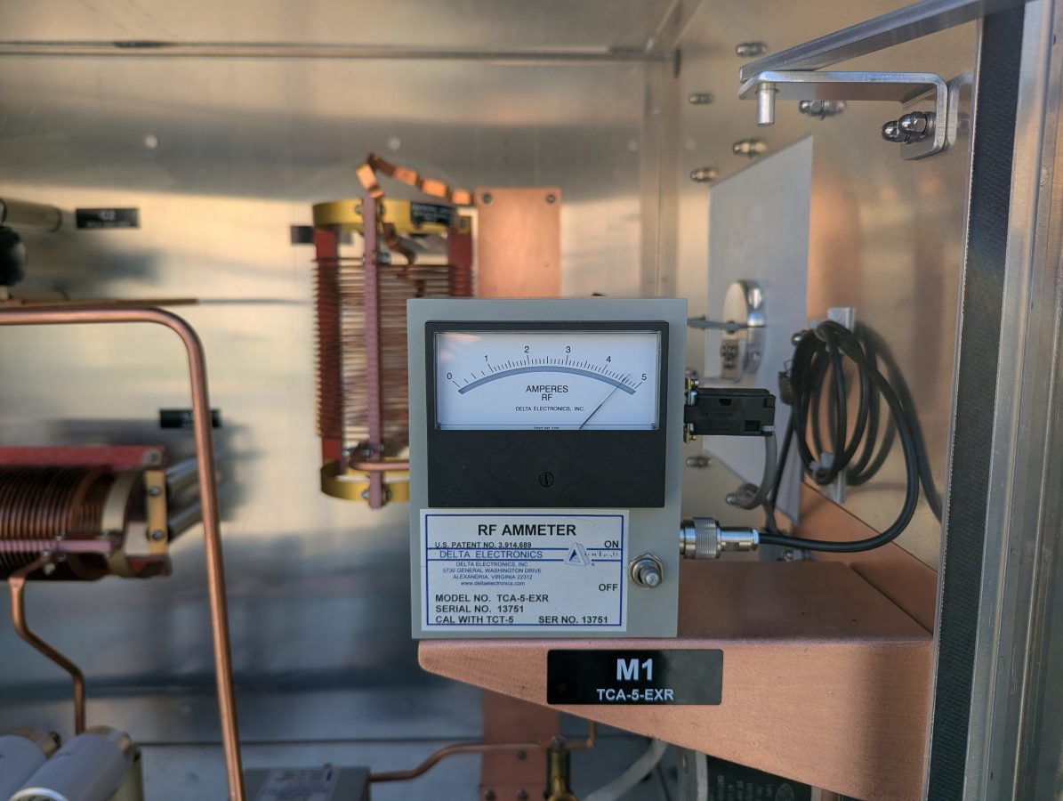
The new base current meter agrees with the impedance measurement.

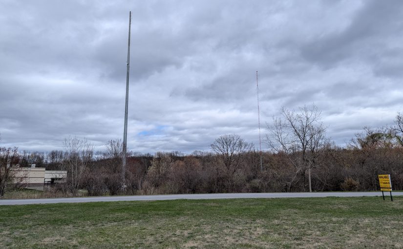

For fun, modeled a lattice tower then a one wire tower over perfect earth in EZNEC using NEC5. The one wire tower because it is lots easier to modify. Feed a single wire under the tower to ground, so no feed with a lightning loop or any such.
R X
Lattice tower 160′ x 2″ f 35.86 5.335
Tower HeightTower diameter ”
140 24 23.25 -50.4
150 24 28.76 -26.27
155 24 31.97 -14.05
160 24 35.53 -1.682
165 24 39.49 10.89
170 24 43.91 23.71
160 12 34.59 -5.29
160 18 35.09 -3.302
160 24 35.53 -1.682
160 30 35.94 -0.466
160 36 36.32 +4.855
Having never detuned a tower found this interesting. Just one question on the detune circuit is it tuned to 1450 or just a random frequency that gives a impedance above 2k?
Thanks for being a great teacher on things I don’t know you will not believe how much I have learned from you.