I pulled this out of the published posts and updated it.
I have been working on updating some wiring at one of our client’s transmitter sites. I noticed that an off air monitor feed was going back to the studio on a Barix box, which is fine. It was being fed from a balanced output of a DA to the unbalanced input on the Barix box. This being at the transmitter site, was susceptible to RF noise. I decided to make a passive audio BALUN.
In any case, there are several ways to go from balanced to unbalanced without too much difficulty. The first way is to wire the shield and Lo together on the unbalanced connector. This works well with older, transformer input/output gear, so long as the unbalanced cables are kept relatively short.
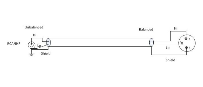
Most modern professional audio equipment has active balanced input/output interfaces, in which case the above circuit will unbalance the audio and decrease the CMRR (Common Mode Rejection Ratio), increasing the chance of noise, buzz, and so on getting into the audio. In this case, the CMRR is about 30 dB at 60 Hz. Also, newer equipment with active balanced input/output, particularly some brands of sound cards will not like to have the Lo side grounded. In a few instances, this can actually damage the equipment.
A Henry Match Box or something similar can be used. I have found, however, the active components in such devices can sometimes fail, creating hum, distortion, buzz, or no audio at all. Well-designed and manufactured passive components (transformers and resistors) will provide excellent performance with little chance of failure. There are several methods of using transformers to go from balanced to unbalanced or vice versa.
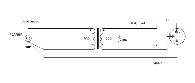
Using a 600:600 ohm transformer is the most common. Unbalanced audio impedance of consumer-grade electronics can vary anywhere from 270 to 470 ohms or more. The 10,000-ohm resistor provides constant loading regardless of what the unbalanced impedance. In this configuration, CMMR (Common-Mode Rejection Ratio) will be 55 dB at 60 Hz, but gradually decreases to about 30 dB for frequencies above 1 KHz.
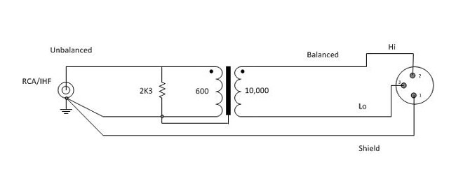
A 600:10,000 ohm transformer will give better performance, as the CMMR will be 120 dB at 60 Hz and 80 dB at 3 KHz, remaining high across the entire audio bandwidth. The line balancing will be far better for the high-impedance load. This circuit will have about 12dB attenuation, so plan accordingly.
For best results, use high-quality transformers like Jensen, UTC, or even WE 111C (although they are huge) can be used. I have found several places where these transformers can be scrounged, DATS cards on the old 7300 series Scientific Atlanta satellite receivers, old modules from PRE consoles, etc. A simple audio BALUN can be constructed for little cost or effort and sound a whole lot better than doing it the wrong way.
A brief list, there are other types/manufacturers that will work also:
| Ratio | Jensen | Hammond | UTC | Edcor |
| 1:1 (600:600) | JT11E series | 804, 560G | A20, A21, A43 | PC600/600 |
| 4:1 (10K:600) | JT10K series | 560N | A35 | PC10K/600 |
Keep all unbalanced cable runs as short as possible. In stereo circuits, phasing is critically important, so pay attention to how the balanced transformer windings are connected.
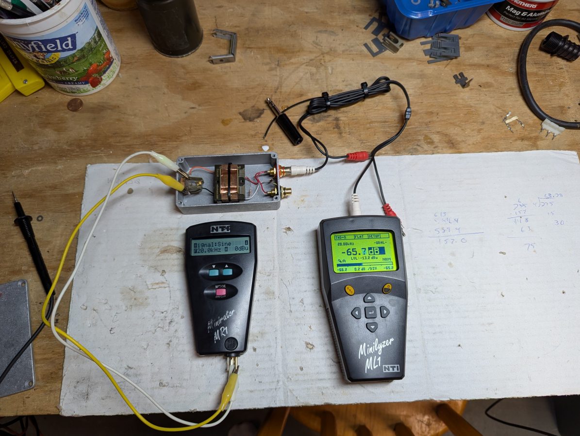
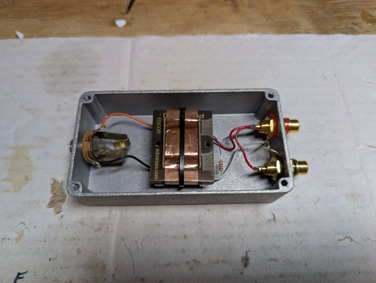
As for cost; I purchased the Edcor PC10K/600 transformer on eBay for $20.00 and the Hammond 1590B Enclosure was about $9.00. The audio jacks and resistor were in the parts drawer. It took about 20 minutes to layout the holes, drill, mount the audio jacks, and solder the jumper wires. I used a tie-base, wire tie, and some Gorilla glue to hold the transformer down. I used a 1/4 inch TRS jack because the enclosure was a little bit too small for an XLR jack. If a stereo pair needed be converted, it would require two of everything.
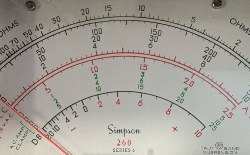
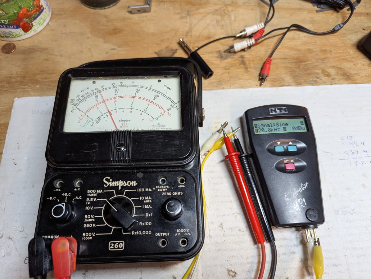
Overall, I fun project. The old Simpson 260 is still accurate!


Thanks. Very clear explanation.
Paul – Very informative, and quite handy to have as a printed page.
For the benefit of other Mom-&-Poppers out there, if you were to do a sequel to your Unbal-Bal page, I might suggest showing how to properly sum a stereo signal (say from a stereo soundcard or consumer-type CD player) to mono with a couple of isolation resistors; a common Y-connector is not a good choice as you’d be forcing current from one output back up into another.
Lots of small market AM’ers might still be using a mono board from the LPB era (or older!) and would need to be able to do this.
Best Regards,
Alan Peterson KJ4IVD
Ass’t CE, Radio America Network
Washington DC
Alan, I’ll work on H-pads and summing networks in one post, at some point when I get some time to write it. As always, thanks for your input.
Hi Paul,
After googling my head off and wasting a lot of precious terra time,
I found your page and it was very clarifying!
This information will save me a lot of hassle on building my passive preamp i am starting right now….
Thanks for sharing your knowledge!
Best regards,
John
The Netherlands
Is it assumed in these diagrams that the unbalanced side is an input, output, or either?
This would be fabulous, Except! The title of the article is “unbalanced to balanced” which is what I need to understand. However the drawings are all titled “balanced to unbalanced”.
Can you clear up the confusion, please?
It is a passive circuit, thus it will work in either direction.
bal to unbalanced
from a sound card balanced with output
Output impedance, XLR, unbal. / bal. 50 Ω / 50 Ω
Output level, XLR, nom./max. +4 dBu / +16 dBu
Output impedance, TRS, unbal. / bal. 50 Ω / 50 Ω
Output level, TRS, nom./max. +4 dBu / +16 dBu
to input in a HAM radio unbalanced
with 20 mV ( 32 dBu level input )
audio trasformer 600/600 1:1
Pi or T pad attenuator from – 36 dBu to + 4 dBu
lot of ideas around but everyone have the true!
can you recomend me something?
ciao
I ran into this driving studio monitors with a consumer sound card. The usual stuff wasn’t working (had CPU noise no matter what) but I found a combination that worked perfectly over a VERY short run. IMHO this would never work over more than 6ft or so:
* Sound card sleeve into both monitor tips
* Sound card tip into L monitor ring
* Sound card ring into R monitor ring
* Monitor sleeve open for experimentation. I had mine connected to the cable sleeves but left open at the head end. Maybe would be quieter if left entirely open on both ends? Perhaps one end tied to a ground somewhere? In my case the PC, studio monitors, and every peripheral were powered by the same AC outlet.
I was trying hard to avoid an isolation transformer — seems just so…. impure and non-linear.
When using the 600 to 10000 ohm transformer, isn’t the 10000 ohm side the unbalanced side of the transformer, not the balanced as shown in your image?
Either way will work. The way I pictured makes a better universal match if the IHF side is not 10K. If you know that the IHF is 10K, then flip it around and get rid of the resistors.
Dear Mr. Paul Thurst,
Could you please advise how about the case of balanced to unbalanced with 10k:600 transformer with center taps in both primary and secondary?
Thank you very much in advance.
Lee, if the center taps of the primary and secondary are left open, then the impedances of the primary and secondary are unchanged.
I understood. Thank you so much, Mr. Paul Thurst.
My transformers don’t have the connection to the iron core. How to connect 2k3 resistor then?
Hi Paul. I have 600/600 unbalance to balanced. I need to attenuate the line level. What is you recommendation should I just series a resistor on the hot side of the line level. Ultimately I wand to drop line level to mic level balanced. Thanks
Graeme, you will need at least 50 dB attenuation to go from line to mic level. I recommend either an H pad or a T pad, depending on where you want the attenuation to occur. I suggest doing this on the balanced side of the transformer, if you are using one. A good H and T pad calculator can be found here: https://www.nu9n.com/tpad-calculator.html
Good Stuff. Thank you.
Not long ago an audio card (no idea what it was 10 years later) touted “balanced IN & OUT” for their breakout.
Both were just a 100 ohm resistor in series with the positive/tip and 100 ohm resistor to ground on the negative/ring of the 1/4 inch jack in the breakout. Caused me issues so bypassed them. Fed unbalanced in.