Slightly off-topic, but includes radio.
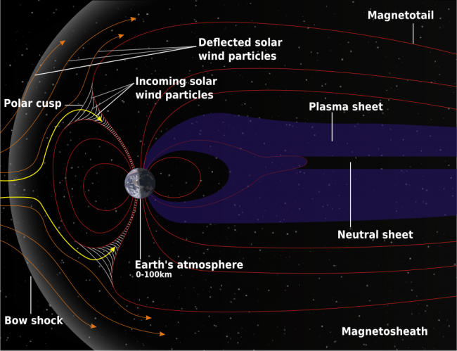
The antennas are the most interesting aspect of Radio Frequency Engineering to me. The transfer of power in the form of voltage and current to the magnetosphere and back again is where the rubber meets the road. Any opportunity to experiment with the art of antenna design and fabrication is welcome.
This is for the Amateur Radio community. With the upswing of Solar Cycle 25, predicted to peak in July of 2025, I decided it would be fun to get back on the air with some type of HF setup.
My past experience with HF radio and peak solar cycles is that wild fluctuations can occur creating band openings at unusually high frequencies or no propagation at all. The geek in me finds this very interesting. HF Propagation is a complex matter. Long-distance communication can be carried out with very low power levels provided the ionosphere is bouncing signals back to the earth instead of absorbing them.
Weak Signal Propagation Reporter (WSPR) is an HF beacon system, where stations transmit a digital signal containing your call sign and Maidenhead Gird locator for several seconds. The challenge is to have an efficient antenna and use as little power as possible. In this case about 200 mW (0.2 watts) or 23 dBm. The modulation type is MFSK and the bandwidth is 6 Hz. According to Wikipedia, which is mostly accurate about things like this; WSPR uses a transmission protocol called MEPT_JT. That sends messages composed of:
- 28 bits for callsign, 15 bits for locator, 7 bits for power level, total: 50 bits.
- Forward error correction (FEC): non-recursive convolutional code with constraint length K = 32, rate r = 1⁄2.
- Number of binary channel symbols: nsym = (50 + K − 1) × 2 = 162.
- Keying Rate is 12000 ⁄ 8192 = 1.4648 baud.
- Modulation is continuous phase 4 FSK, with 1.4648 Hz tone separation.
- Occupied bandwidth is about 6 Hz.
- Synchronization is via a 162-bit pseudo-random sync vector.
- Each channel symbol conveys one sync bit (LSB) and one data bit (MSB).
- Duration of transmission is 162 × 8192 ⁄ 12000 = 110.6 s.
- Transmissions nominally start one second into an even UTC minute: e.g., at hh:00:01, hh:02:01, etc.
- Minimum S/N for reception is around –34 dB on the WSJT scale (2500 Hz reference bandwidth).
Distant stations report reception to a database. Several good websites display reception in a map or table format.

This map shows a good path to coastal Maine on 40 meters. The received signal-to-noise ratio is -2 dB at a distance of 423 KM.

My antenna is an End Fed Half Wave (EFHW) cut to 3.568 MHz which can be used on any harmonically related frequency (7, 10, 14, 18, 21, 24, and 28 MHz). To accomplish this, a 49:1 Unun (Unbalanced feed to unbalanced feed) transformer is used to transform the 2,400-ohm impedance of the wire to the 50-ohm impedance required by the transmitter. The antenna works best against a ground system that is not less than 0.05 wavelength or 18 electrical degrees on its lowest frequency. That works out to about 4.2 meters (14 feet). A little bit longer is a little bit better. Six 20-foot long 14 gauge bare copper ground radials are attached to an 8-foot ground rod.

The Unun is two FT240-52 (not an affiliate link) cores with 14 gauge enamel wire consisting of 2 turns on the primary and 14 turns on the secondary. The antenna is 40 meters (132 feet) of 10 gauge hard-drawn stranded copper wire. This should be good for about 800 watts CW/SSB on HF if I want to use it in that capacity.


There are several guides on how to make the unun available via Google search. There is some debate on whether a 64:1 transformer should be used. Most indicate a 49:1 is the best match. The diecast aluminum (not an affiliate link) enclosure is a nice feature. It cost $33.00 on Amazon.
I used the network analyzer to trim up the antenna a bit. I made a few measurements, the first was just the wire with no ground connected. The next was the wire and ground system after trimming the length for resonance on 3.5 MHz.
The transmission line is LMR-400 with N connectors. I loath PL-259s and use N connectors whenever possible.
I did a series of broadband SWR sweeps. The first was just the wire prior to trimming.

The next was with a ground rod and six ground radials, #14 bare copper wire twenty feet long.

This demonstrates the effect of a good ground system. It is worth the effort (and it is an effort) to put in some buried ground radials with this type of antenna. I think above-ground radials would work too.
Here is a screenshot of the little Zachtek desktop WSPR beacon transmitter I bought. This is a great addition to the toolbox and works well for testing the radiation efficiency of an HF antenna. It has a GPS antenna input for timing and location reference. The frequency bands are selectable if you are testing a mono-band antenna. It will work into a fairly poor load, so I suggest sweeping the antenna first with an analyzer.


This shows that my signal is getting out. So far, the furthest distance is 17,030 km with an SNR of -10 (Australia, VK5ARG). That is quite amazing when you think about it. I am letting this run overnight to see how the propagation changes. Overall, this was a good recreational project and now I have a known working HF antenna.


Man, I WISH I had that much room for skyhooks. The rig and antenna are down here for annual maintenance, but I was doing WSPR receive-only with WSJT-X software a couple months back. Off-center fed 40M dipole up ~20′, Kenwood TS-440S, and occasionally a Drake 1A. Yep, once warmed up, that 1959 Drake does work on WSPR, PSK-31, SSTV, etc.
I was rather amazed at the signals from Central and South America being decoded here. Even copied some activity from Michigan and Florida on the 630 Meter band! It’s kinda like having your own MF/HF chirpsounder, lots of fun.
Paul, welcome to WSPR – have been playing with this mode over 11 years at W1CK here in Oceanside, CA. Dozens of antennas LF through 10M deployed and tested on the roof of our two story industrial building over the years.
Have run WSPR LF TX (~ 137.4 KHz) on a 23′ tall roof mount wire vertical with building roof steel as ground system – TX at .5W close to the 1 Watt EIRP limit for amateur LF band. That required some work – end result was a class D amp with ~200 Watt LF output into a Litz wire loading coil at the base of the vertical. Imagine a Tesla coil into a short whip antenna to get a sense of the high RF voltage on that antenna when tuned to resonance (~15 KV) but was heard as far as the East coast on good evenings, and avoided any nasty arcing with lots of Teflon insulation!
I found that the steel structure underlying the roof here approximates the performance of an elevated ground plane (without radials) that works very well up through 80M. Access to an unused AM tower would be the ultimate test for LF/MF. If only I knew someone…
Crusty, those old Drake units (Collins too) are built like a tank. Not surprising that they would work with modern modes. Speaking of chip sounders; back in the day (in the Coast Guard) we would have given almost anything for real-time information like this.
Steve, that is fantastic! There may be a 500 KHz tower at KPH that could be “borrowed” for a brief period.
Paul, I’ve been heard by KPH many times – they operate pretty close to all band WSPR RX 24/7 – need to make it up there someday and ask nice!
Your 40M .2W sig spotted here twice (3870 km exactly due west of you) on a 6′ whip with wideband low noise amp at base. Data below from wsprnet.org:
Timestamp Call MHz SNR Drift Grid Pwr Reporter
2024-06-11 08:26 KH2R 7.040178 -20 0 FN21us 0.2 W1CK
2024-06-11 03:46 KH2R 7.040122 -22 0 FN21us 0.2 W1CK
Steve,
I am still amazed by how far some of these signals travel with 200 mW. 40-Meters regularly makes it to Europe and South America and there was one 80-meter reception in Antarctica (DP0GVN)
2024-06-08 00:52 KH2R 3.570201 -24 0 FN21us +23 0.200 DP0GVN IB59ui 13551
I am working on something for MF for the fall or winter.
Great on DP0GVN – the German Antarctic Neumayer III Station – have found them to be a good indicator on 80M of promising lower band conditions along with EA8BFK in the Canary Islands on a given night.
In the winter, amateur MF WSPR (475.6 KHz) tends to open up to the mid Atlantic East coast from here (West coast) after 2100 local time. It often favors one way propagation earlier – we can hear East coast, but they can’t hear us. A few hours later I’ve found propagation usually works equally in both directions and NY / New England contact is sometimes possible.
If you build a vertical, look at using an RF ammeter with a remote current transformer for base current measurement – as opposed to a thermocouple RF ammeter – for all the same reasons that AM stations do.
The used Delta TCA-5EX here is quite accurate at amateur MF through 80M even on short antennas and works at LF but reads low there due to low end response roll-off in the TCT-5 transformer. 5 Watts EIRP at 475.6 KHz on the 23′ vertical here is ~4 Amps of base current given the low input R of that short antenna. Q is high, so narrow bandwidth and Zin subject to significant change with weather conditions.
Roof resurfacing is going on here currently so TX antenna is down for a few weeks, but we’ll be back up by the fall – may see you then..
We have several of those Delta base current meters that have been removed from service. That is good advice. This is a fall project due to time constraints. Good luck with your roof work!