Proper drive levels for a Harris SX series transmitters

I was working on a Harris SX5 the other day and snapped a picture of the scope while measuring RF drive levels.  There are still quite a few of these units out in the field, judging from my search engine results.  I thought it would be helpful to post something about it.  The RF power amp boards for the Harris Gates solid-state AM series transmitters are the same design, I believe.

In order to fully drive the RF MOSFETs in this particular series of transmitters (Harris SX1, 2.5, and 5 including A models) at least 26.5 volts peak to peak is required.  Less than that and the device will turn full-on and internally short.  To measure RF drive, the transmitter must be in local with control voltage on, with the rear door interlock defeated (this can be safely done if the transmitter is wired with separate AC feeds for control and RF power supply). Make sure the RF power supply is defeated and will not turn on.  Measure across the input of each of the toroids that feed the gates of the RF devices.
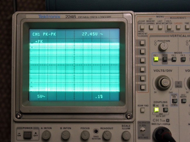
Harris SX series transmitter drive level test
Harris SX series transmitter drive level test, 27.45 volts, 1,110,000 Hz

It should measure between 26.5 and 29.5 volts. This one measures 27.45 volts peak to peak. Each input toroid on every PA board should be measured as the toroids themselves have strange failure modes and may pass resistance and continuity tests, yet still not provide proper drive voltage to the attached devices. This has to do with core permeability.  Each toroid feeds two RF MOSFETs, replace part is IRF-350.

As always when dealing with an SX transmitter, good luck.

We are off the air!

A phone conversation that occurred one Saturday morning:

DJ: (answers hotline) Hello?

Myself:  This is Paul from Radio Engineering Services, you called the answering service and said you are off the air.

DJ: Yes!  The red bat light is flashing and everything!

Myself: Okay, did you try to put the backup transmitter on?

DJ: No.  I didn’t want to mess anything up.

Myself:  You are off the air; I don’t know how things can be more messed up than that

DJ: (laughing) Okay, you’re right.

Myself: Do you have the directions for the backup transmitter?

DJ: Yes, they are right here

Myself: Okay, go ahead and do that, I will call the local engineer and see if I can get him out to the transmitter site, then I will call you back.

DJ: Okay, thanks.

The good news is the backup transmitter came on and they were back on the air.  It is also nice to know that the station has a live DJ on Saturday morning at 7:00 am, many do not.  The main transmitter power outage was likely due to a utility company transient, the area had suffered an ice storm the day before and they were out restoring power that morning.

At least this was a real emergency, I used to get calls at home that the headphone jack on the console was loose.  I took the home phone number down after that.

As requested: The old WSBS studio building

Alan asked if I should ever find a picture of the old WSBS studio building to publish it.  Here it is:

WSBS old studio building

I found this above the coffee machine in the lobby, nicely matted and framed.  I didn’t want to ruin the framing job, so I took a picture of the picture under glass and cropped it, so thus the quality could be better.

I believe this is the original tower from 1959.  The current tower stands on a taller concrete pedestal and is further away from the road.  I think the roadway was widened and raised at some point, thus the new building sits higher in relation to the tower base.  In any case, it little bit of radio history.

Oh damn, La cuarta parte

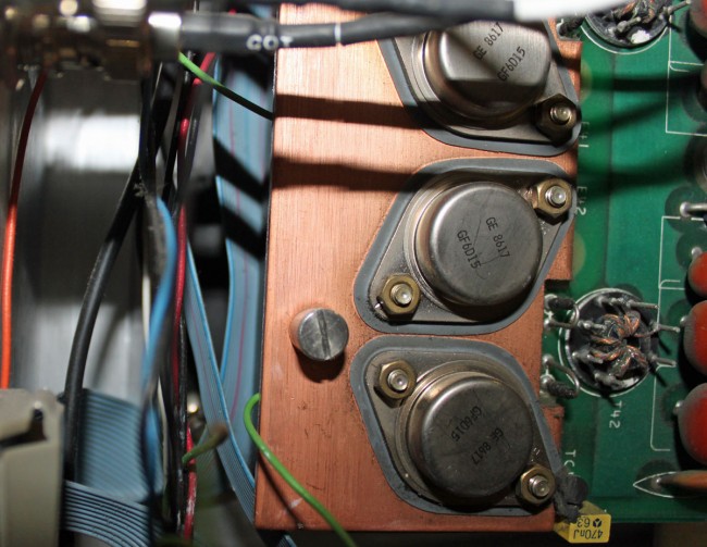
Today there will be a quiz.  Ready?  Look at this picture and see if you can spot the problem:

Problem with Harris SX2.5A transmitter

If you said “Hey, that green wire seems a little odd; it disappears behind the heat sink next to that screw then reappears again at the top,” you are correct.  What really sucks is the green wire is the transmitter off connection to the remote control.  So, when the PA board was secured to the heat sink, the wire was trapped between the board and the heat sink.  Since the components were cold, they did not pinch through the insulation right away, no.  Rather, after the transmitter ran for several hours at full power, it got hot enough to displace the wire insulation and cause a short.  Doh!  The transmitter is off and it won’t come back on!

This is a picture of the wire after it was removed:

Pinched wire
Pinched wire

Haste makes waste.  Unfortunately, it was someone else’s haste that ruined my Saturday afternoon when I was supposed to be taking my son to little league practice.  I am sure that some not-so-kind words will be exchanged very soon.

Always double-check your work.