How the Cold War was won

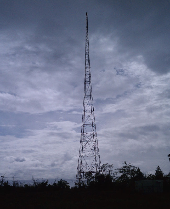
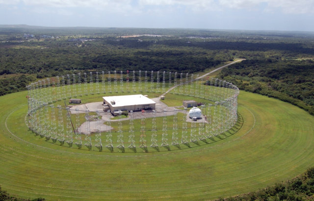
This is not really apropos radio broadcasting, but it is about radio and it has a lot to do with engineering.  Back in the day, as a young man out to do whatever it was, I ended up being stationed on Guam, working at the Coast Guard radio station there.  That was interesting work, to be sure, but every morning and evening, either on my way to or from work, I would drive by this, which looked very interesting:

AN FRD-10 NAVCAMSWESTPAC, Guam

I had to lift the photo from a Navy Radio history site.  Back in my day, aiming or even possessing a camera around this area or building would likely inflict the extreme ire of the Marines, who attentively observed the area and were ready to call down a painful lesson to all not obeying the “NO PHOTOGRAPHY ALLOWED” signs.

Nicknamed “The Elephant Cage” it is a Wullenweber antenna used for high-frequency direction finding (HFDF) and was part of a system called “Classic Bullseye.”  There were several of these systems across the Pacific Ocean, and they all worked together using a teletype network.  The Army-Air Force version was called a AN  FLR-9, which was slightly larger.

AN/FRD-10 antenna layout

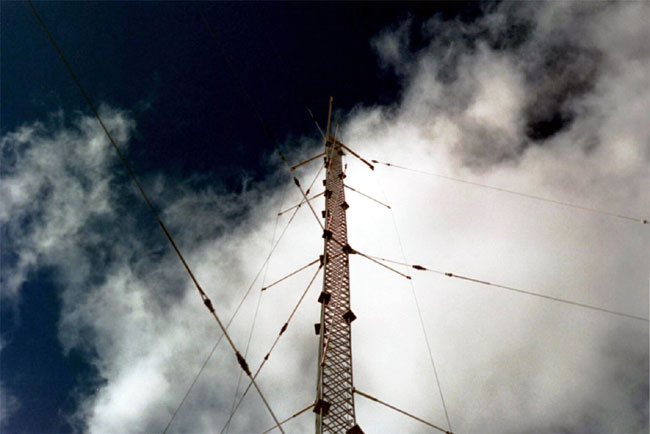
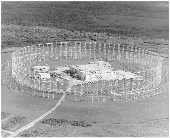
There were two concentric rings of antennas, the tallest being the closest to the center building and used for the lowest frequencies.  It covered from about 1.5 to 30 MHz.  The rings consisted of several individual antennas, all coupled to a Goniometer with coaxial cables cut to identical lengths.  The outer ring had 120 vertical-sleeved dipole antennas, and the inner ring consisted of 40 sleeved dipole antennas.  The inner ring of towers also contained a shielding screen to prevent the antennas on the other side of the array from picking up signals from the back of the antenna.  A radio wave traveling over the array was evaluated and the Goniometer determined the first antenna that received the signal by comparing phase relationships.   The ground system was extensive.  Immediately under the antennas was a mesh copper ground screen.  From the edge of the copper mesh, buried copper radials and extended out 1,440 feet from the building.

The effective range for accurate DF bearings was about 3,200 nautical miles, which equates to about two ionospheric hops with the angle theta between 30 to 60 degrees referenced to the ground.

It was quite effective, it only took a couple of seconds to get a good bearing.  If the other stations on the network were attentive, a position could be worked out in less than 10-15 seconds.

AN FRD-10 transmission line diagram
AN FRD-10 ground diagram

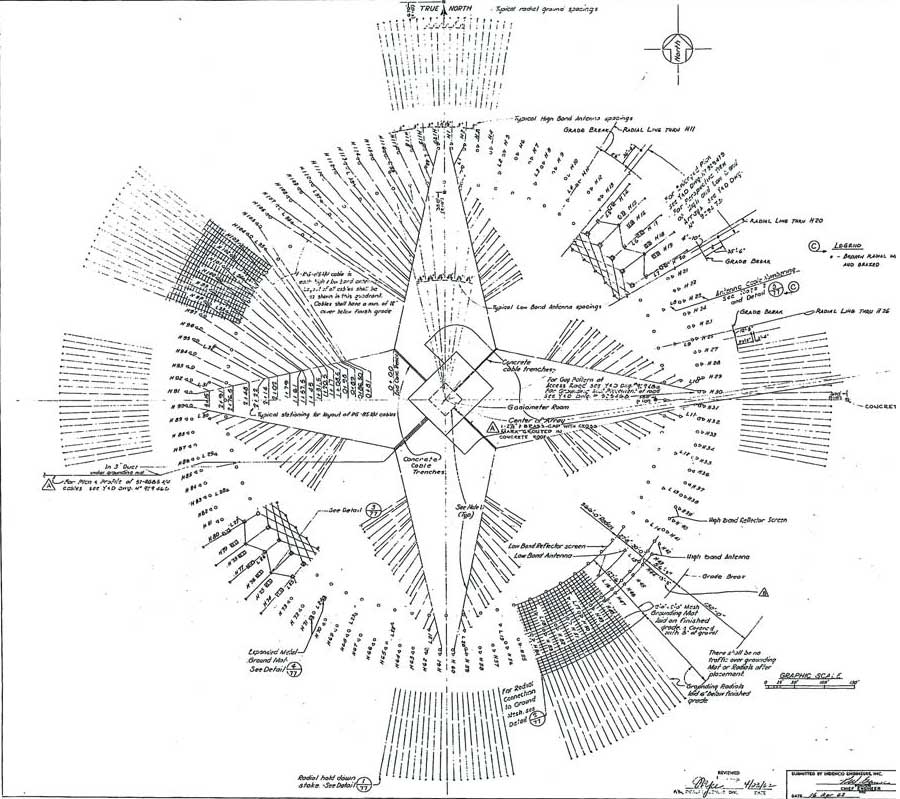
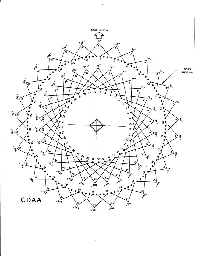
It is a little hard to read, but this is the ground layout of the AN FRD-10 CDAA.  The transmission lines to each antenna are shown, along with the ground screen and building in the center of the array.

We Coast Guard types used this mainly for Search and Rescue (SAR) and the occasional Law Enforcement (LE) function.  I believe we actually saved a few lives with this thing.  I found the Navy operators to be very helpful, I think some of them enjoyed the change of targets from their normal net tripping.

The Navy operated AN FRD-10s at the following locations in the Pacific:

  • Imperial Beach, CA (south of San Diego)
  • Skaggs Island, CA (northeast of San Francisco)
  • Hanza (Okinawa) Japan
  • Waihawa, HI
  • Finegayan, Guam
  • Adak, AK
  • Marietta, WA

The Air Force/Army installed AN FLR-9’s in the following Pacific Locations:

  • Missawa AB, Japan
  • Clark AB, Philippines
  • Elmandorf AFB, AK

Basically, there was no corner of the Pacific Ocean that could not be listened to and DF’d.  Some people look back nostagically at the cold war when we “knew who the enemy was,” so to speak.  I am not one of those.  They either didn’t really know the enemy or have conveniently forgotten some of the less endearing qualities of the Soviet Union.

I believe all of these systems have been decommissioned and most have been taken down and scrapped.  The National Park Service studied the Waihawa, HI system as a part of their Historical American Building Survey (HABS HI-552-B2) (large .pdf file) before it was torn down.  Good technical description and building pictures.  Near the end of the report, it is cryptically noted that:

Beginning in the mid-1990s the NSG (ed: Naval Security Group), noting the absence of Soviet targets and wanting to cut costs and change the focus of its SIGINT collection, began closing FRD-10 sites… Undoubtedly, since the September 11, 2001 terrorist attack on the World Trade Center and the Pentagon, listening posts have gained importance and most likely increased in number and sophistication. The FRD-10 CDAA at NCTAMS Wahiawa ceased listening in August 2004; it can only be assumed the closure occurred because there was a better way to do it.

Indeed.

The Guam site has been stripped out and abandoned, the latest photo I can find is from 2008:

Abandoned AN FRD-10, Finegayan, Guam

And people think AM broadcasting is expensive…

The Devil is in the details

Sometimes it is the seemly small insignificant detail that will take a station off the air. To expound on that a bit, I have my own story which happened yesterday.  The back story is this:  About three years ago, some unauthorized tower climbers climbed the WICC south tower all the way to the top.  The station remained on the air at full power while this was going on.  Once at the top of the three hundred-foot tower, the climber, we can call him “Crack Head,” managed to loosen, then remove the beacon and throw it to the ground.  Mind you, this guy had no safety climbing equipment whatsoever and he had to stand on the top plate, which is all 20″ x 20″ square, of which the beacon takes up 16 inches.  A two-inch purchase between himself and eternity demonstrates that God does indeed smile on fools and drunks.

WICC south tower with long island sound in background
WICC South tower with Long Island sound in the background

Fortunately, his friend on the ground had a video camera and filmed the entire episode.  Even better, they then posted it on Youtube.   The police took interest in this video and its owners because the damage to the radio station was significant, and with the tower being about a mile away from the end of the Stratford Airport runway 17, presented a real hazard to air navigation.  Needless to say, the video was used by the prosecution and both crackheads are now in prison, God having limits after all.

A spare beacon was hoisted to the top of the tower and placed in service.  This beacon was quite old and leaky and continually failed, burning out the tower light flasher.  Thus, it was time to replace it.  We took advantage of the outstanding weather and the crew from Northeast Towers made quick work of it.  Removing and lowering the old beacon to the ground, then hoisting the new beacon up and installing it.  I goobered it by not taking pictures of the beacon fixtures flying up and down the tower.  I took the station off the air for about five minutes to check the condition of the wiring going up the tower, making sure there were no shorts up the tower or back toward the transmitter building.  While I was doing this, I overheard the two-way radio conversation between the tower climber and the ground crew on wiring.  It seems the old beacon had only two wires, hot and neutral.  The new beacon had three wires, hot, neutral, and ground.  Tie the neutral and ground wires together, instructed the tower boss.

Nothing more was thought of that, it sounded okay to me.  Unfortunately, the tower had other ideas.  About an hour after we secured from the job and drove away, the station went off the air.  It seems the neutral wire was not referenced to the tower previously.  Because now the neutral wire was tied to the top of the tower, the RF found a path to the ground via the tower lighting choke at the base of the tower.  It started arcing to its access door causing the transmitter to go off around 4 PM.  Equally unfortunate was the fact that the construction gate was closed and I had to get a boat ride with the harbor master, which took about an hour to arrange.  The entire situation was further complicated by darkness, which comes predictably around 6:30 PM this time of year.

When I arrived back out at the base of the tower, I took the metal access door off of the tower light choke cabinet.  I could see the fresh track marks all across the bottom of the door. With the door off, I turned the transmitter on.  Worked just fine.    I tried cleaning it off with a Scotch Bright, but to no avail, the transmitter would not run at any power level with the door in place.

Finally, the harbor master becoming impatient and darkness quickly falling, I taped a garbage bag over the tower light choke box with the door off and turned the transmitter back on.  The tower crew will have to come back and remove the ground wire on the beacon.

The first rule of troubleshooting: Check the last thing that was worked on first.

Update:  And look, here is the original story in Radio World: Tough times a Pleasure Beach.

The folded Unipole antenna

In the 1990s, the folded unipole antenna was touted by many to be the savior of AM radio.  There were many claims that a folded unipole antenna did not need a complicated ground system, a simple ground rod at the base of the tower would work fine.  That turned out to be not exactly the case.   Kintronic did a study (.pdf) that basically dispelled that notion, along with several others.   The folded unipole antenna performed within a few percentage points of a series-fed tower under the same testing conditions.

three wire folded unipole on a guyed tower

Folded unipoles do have the advantage of a grounded tower.  Grounded towers have a distinct advantage in lightning-prone areas, such as central Florida.  I can attest through my own experience, a series-fed tower is much more likely to induce lightning damage to a transmitter or ATU.  Folded unipole tower systems can also be used to co-locate other antennas, such as STL, cellular, PCS, etc.  Making some extra rental money on an AM tower is not a bad way to go.

I began fooling around with MANNA-GAL, which is a NEC-2-based program.  It is a free ham radio program, so it is a little clunky to use and it took a while to figure out, but once I did, it is fun.  I modeled a unipole antenna for medium wave use and the results are pretty interesting.  First of all, I drew out X-Y part of the system on graph paper because the program requires all wires (elements) to be entered in a coordinate-based format.  The Z axis is the tower, since there is only one of those, that was easy.  I played around with series vs. unipole systems and the results were fairly close to what they are supposed to be.  One of the nice things about MANNA-GAL is it allows the user to change the ground conditions.  To add a unipole to the tower, I put 3 wires spaced one to two meters away from the primary Z-axis wire, connected them to the top of the tower, and changed the drive point to the skirt wires.

The interesting part is when I added an above-ground counterpoise instead of a buried radial ground system.  I think Ron Nott, of Nott, ltd. did much of this work too.  What I found was that with between 5 – 10 above-ground radials of 90 degrees or greater, the efficiencies are within about 10 percent of theoretical for a 120-buried radial system.  Again, the ground conductivity plays a big role in this, poor ground conductivity will reduce efficiencies equally for both systems.

As the tower height approaches 110 degrees or so, depending on the spacing from the tower of the skirt wires, the bandwidth really starts to open up.  At 110 degrees the base impedance is about 120 ohms with about 80 ohms inductive reactance.   Both the impedance and reactance slope slightly upward with frequency but are linear +/- 50 KHz of the carrier.  This slight asymmetrical sideband distribution can be easily canceled out in the ATU with a few degrees of negative phase shift through the T network.

Again, all of this is theoretical, but I have found that NEC is usually within +/- 10% of real-world values.  It is difficult to get a handle on ground conductivity unless measurements are taken.  Even from season to season, that can change.

The above-ground counterpoise requires a partial proof, according to FCC 73.186.  If this were a directional station, this would be required anyway.  For a non-directional station, it is pretty easy, for six radials, it would probably take about one to two days of driving around with a FIM 41.  The other consideration is public exposure to RFR from the radials.  This can easily be measured with a NARDA meter.  More radials will spread the induced currents out more, for higher-powered stations, 10 above-ground radials might be required.

There are several radio stations in the country that are successfully using above-ground counterpoises.  It seems to be a good system and requires much less material and labor to install than the traditional ground system.

Therefore, if I were designing a new AM station, I’d use a grounded tower between 105 and 110 degrees with a unipole and 6 above-ground radials 90 degrees or greater.

Common Alert Protocol (CAP)

Since the FCC started the CAP clock ticking on September 30th, there has been a flurry of activity regarding the manufacture and installation of CAP equipment.  CAP is integrated into something called IPAWS, which stands for Integrated Public Alert and Warning System.  In other words, CAP is the vehicle that IPAWS uses to get information broadcast through radio, TV, Cable systems, etc.  IPAWS encompasses all alert types including cellphone, texting, e-mail, and landline phone calls.  Many states, including New York State, already do this.  FEMA spells out the reason for IPAWS:

The advent of new media has brought a dramatic shift in the way the public consumes information. IPAWS, as the next generation emergency alert and warning system, capitalizes on multiple electronic media outlets to ensure that the public receives life-saving information during a time of national emergency.

Historically, the public depended exclusively on radio and television to receive alerts, but current research shows that the reach of radio and TV is less than 40% of the populace during the work day. While less than 12% of the population is watching TV in the middle of the night, an even smaller number is tuned into the radio, at 5% of the populace. Television and radio will continue to be valuable sources of public information, but their reach is decreasing. Further, these information sources can only target a state or regional sized area and do not encompass alerting for people who do not speak English or those with disabilities, including the 29 million suffering from hearing impairment.

Today, the internet, including video and email, and cellular and residential phones are increasingly popular and therefore, valuable, sources of information. One study showed that the Internet has a 62% usage rate, averaging at 108 minutes a day. While television remains the most popular source for information, the Internet ranked either first or second at both work and home.

CAP figures into this by acting as a method to move data between IPAWS and EAS.  The basic CAP converter polls a CAP server, somewhere, for messages.  When a message for a geographic area is received, the CAP converter processes it and converts it to an EAS format, which is then sent via high-level audio to the station’s EAS encoder decoder unit.  The EAS unit receives the information and then has the final say (or station personnel if the EAS unit is in manual) as to whether the EAS message gets transmitted.

FEMA will be setting up a national CAP server in the next month or so, expect an announcement from them in November.  Each state can also set up a CAP server for state and local government use.  This will be implemented on a state-by-state basis.  Currently, there is no information on the New York State Emergency Management Office’s (NY SEMO) website, hopefully, they are aware of all of this and will be updating their system shortly.

The CAP converters installed in individual stations will access the CAP servers via secure HTTP connections.  They will also be able to download software updates from the manufacturers via the same method.