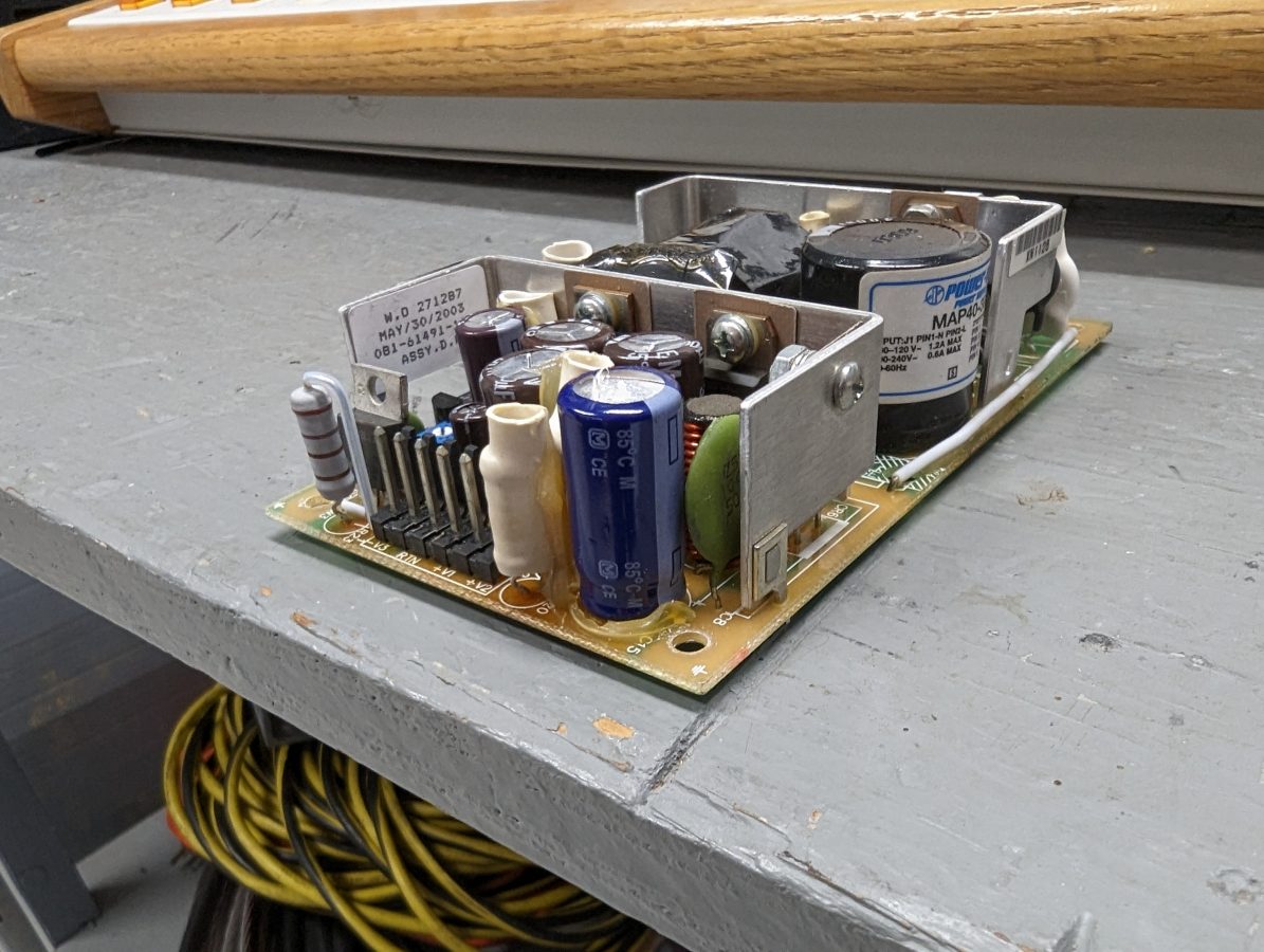
This particular power supply is used in Broadcast Electronics AM1A, AM2.5E, AM5E, AM6A, AM10A, FM1C, FM10T, FM20T, FM30T and FM35T transmitters. It is a Computer Products NFN 40-7610, 40 Watt, +5 VDC, +/- 15 VDC BE part number 540-0006.
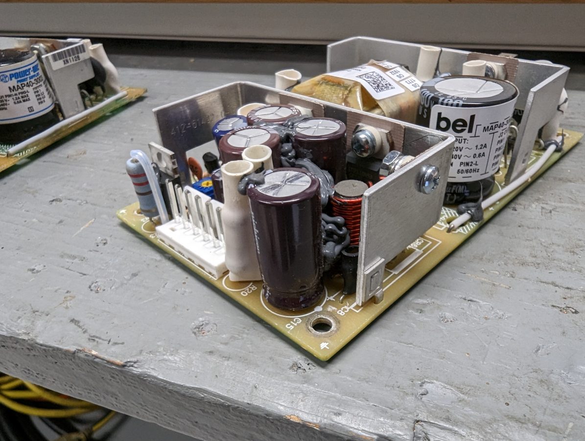
Generally, one component fails over time on this unit, C-15 which is a 680 uF 35 V electrolytic capacitor. When that capacitor dries out, the power supply will fail to start, do odd things like start and fail after a second or two, or cycle on and off. This will happen after the transmitter has been off for a few minutes. Replacing C-15 with a 1000 uF 50 V capacitor will fix the problem. There is enough room for the larger capacitor if the leads are left a little bit long.
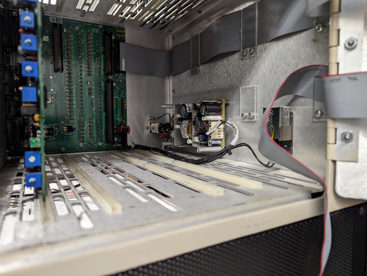
We have several of these repaired units on various shelves at various transmitter sites.
As always, when replacing electrolytic capacitors, pay attention to the polarity otherwise this will happen:
I suppose somebody was in a hurry to get home that day. After I installed this repaired unit, it ran for about 15 seconds and then there was a pop. I opened the door on the ECU and white smoke was wafting out from under the power supply cover. Since the Pope is still The Pope, I knew it was the electrolytic capacitor.
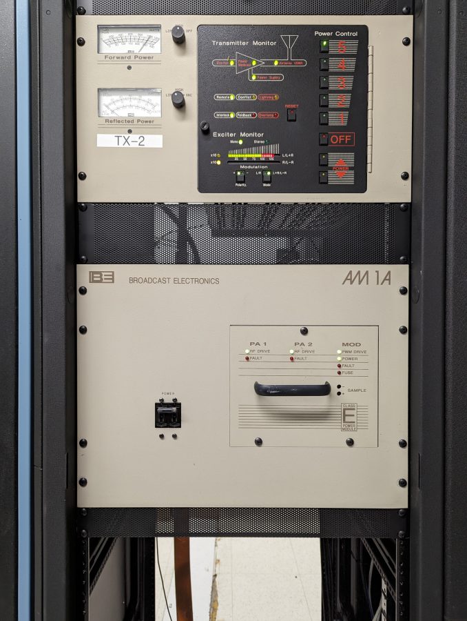
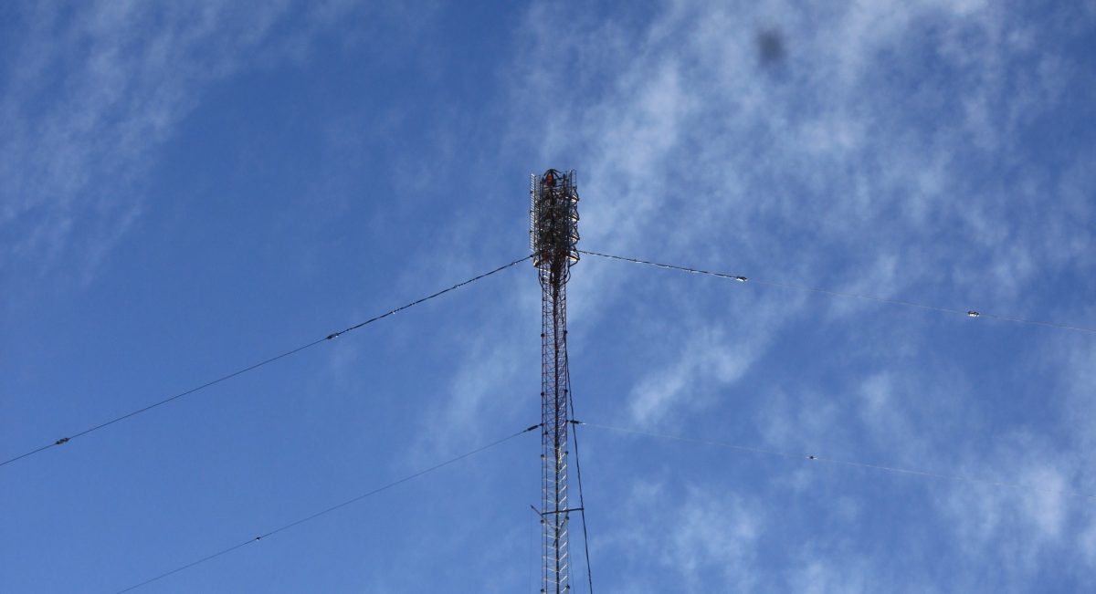
Our beloved BE AM1A is back in service. This transmitter is 22 years old and we can keep it going for as long as parts are available.