The Devil is in the details

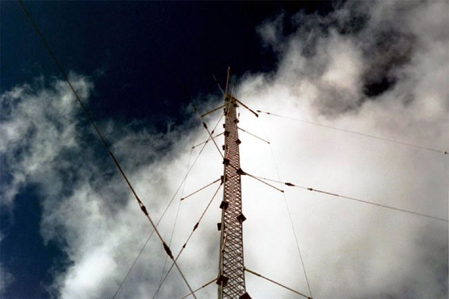
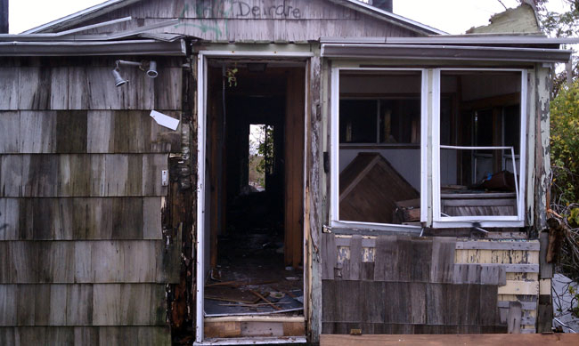
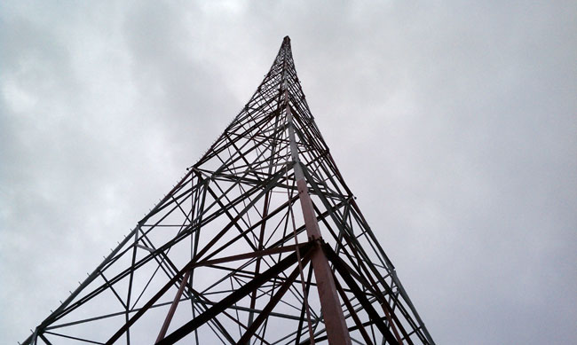
Sometimes it is the seemly small insignificant detail that will take a station off the air. To expound on that a bit, I have my own story which happened yesterday.  The back story is this:  About three years ago, some unauthorized tower climbers climbed the WICC south tower all the way to the top.  The station remained on the air at full power while this was going on.  Once at the top of the three hundred-foot tower, the climber, we can call him “Crack Head,” managed to loosen, then remove the beacon and throw it to the ground.  Mind you, this guy had no safety climbing equipment whatsoever and he had to stand on the top plate, which is all 20″ x 20″ square, of which the beacon takes up 16 inches.  A two-inch purchase between himself and eternity demonstrates that God does indeed smile on fools and drunks.

WICC south tower with long island sound in background
WICC South tower with Long Island sound in the background

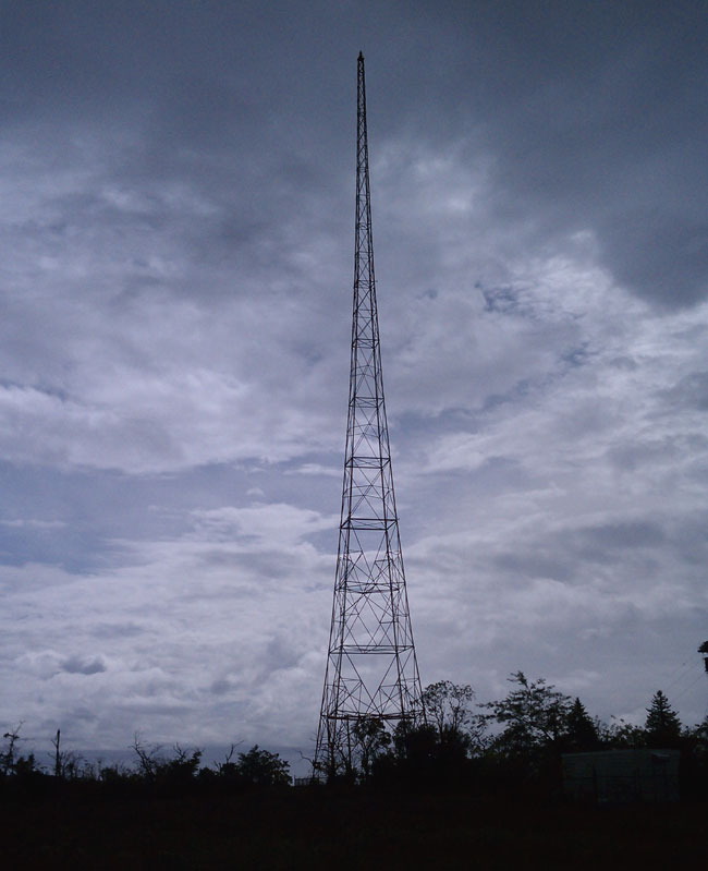
Fortunately, his friend on the ground had a video camera and filmed the entire episode.  Even better, they then posted it on Youtube.   The police took interest in this video and its owners because the damage to the radio station was significant, and with the tower being about a mile away from the end of the Stratford Airport runway 17, presented a real hazard to air navigation.  Needless to say, the video was used by the prosecution and both crackheads are now in prison, God having limits after all.

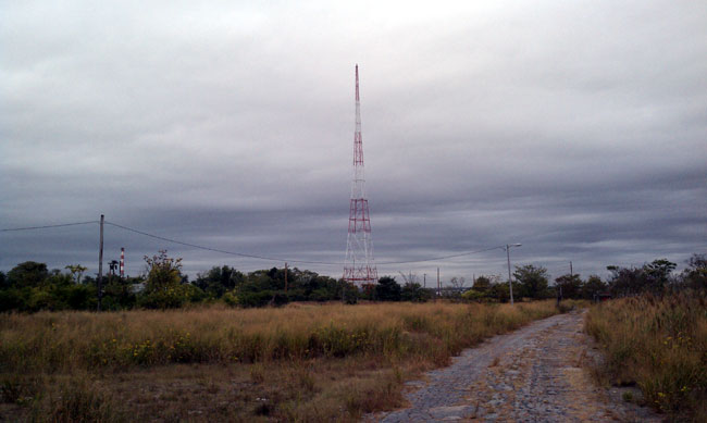
A spare beacon was hoisted to the top of the tower and placed in service.  This beacon was quite old and leaky and continually failed, burning out the tower light flasher.  Thus, it was time to replace it.  We took advantage of the outstanding weather and the crew from Northeast Towers made quick work of it.  Removing and lowering the old beacon to the ground, then hoisting the new beacon up and installing it.  I goobered it by not taking pictures of the beacon fixtures flying up and down the tower.  I took the station off the air for about five minutes to check the condition of the wiring going up the tower, making sure there were no shorts up the tower or back toward the transmitter building.  While I was doing this, I overheard the two-way radio conversation between the tower climber and the ground crew on wiring.  It seems the old beacon had only two wires, hot and neutral.  The new beacon had three wires, hot, neutral, and ground.  Tie the neutral and ground wires together, instructed the tower boss.

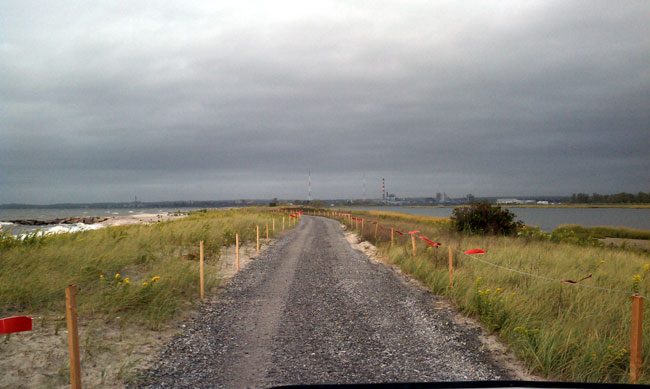
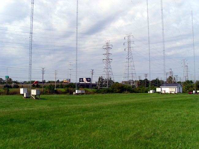
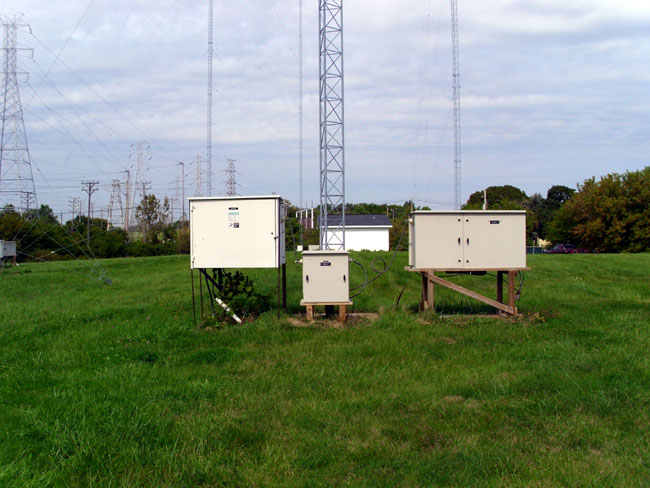
Nothing more was thought of that, it sounded okay to me.  Unfortunately, the tower had other ideas.  About an hour after we secured from the job and drove away, the station went off the air.  It seems the neutral wire was not referenced to the tower previously.  Because now the neutral wire was tied to the top of the tower, the RF found a path to the ground via the tower lighting choke at the base of the tower.  It started arcing to its access door causing the transmitter to go off around 4 PM.  Equally unfortunate was the fact that the construction gate was closed and I had to get a boat ride with the harbor master, which took about an hour to arrange.  The entire situation was further complicated by darkness, which comes predictably around 6:30 PM this time of year.

When I arrived back out at the base of the tower, I took the metal access door off of the tower light choke cabinet.  I could see the fresh track marks all across the bottom of the door. With the door off, I turned the transmitter on.  Worked just fine.    I tried cleaning it off with a Scotch Bright, but to no avail, the transmitter would not run at any power level with the door in place.

Finally, the harbor master becoming impatient and darkness quickly falling, I taped a garbage bag over the tower light choke box with the door off and turned the transmitter back on.  The tower crew will have to come back and remove the ground wire on the beacon.

The first rule of troubleshooting: Check the last thing that was worked on first.

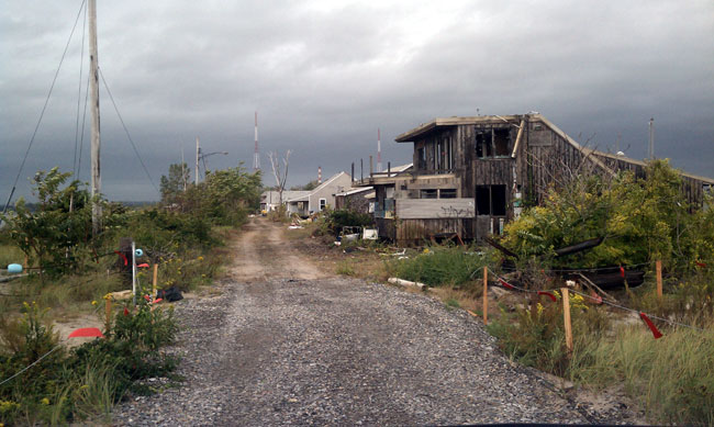
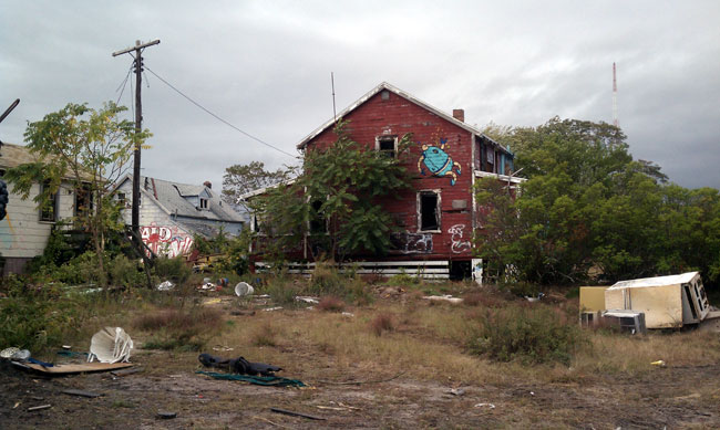
Update:  And look, here is the original story in Radio World: Tough times a Pleasure Beach.

The folded Unipole antenna

In the 1990s, the folded unipole antenna was touted by many to be the savior of AM radio.  There were many claims that a folded unipole antenna did not need a complicated ground system, a simple ground rod at the base of the tower would work fine.  That turned out to be not exactly the case.   Kintronic did a study (.pdf) that basically dispelled that notion, along with several others.   The folded unipole antenna performed within a few percentage points of a series-fed tower under the same testing conditions.

three wire folded unipole on a guyed tower

Folded unipoles do have the advantage of a grounded tower.  Grounded towers have a distinct advantage in lightning-prone areas, such as central Florida.  I can attest through my own experience, a series-fed tower is much more likely to induce lightning damage to a transmitter or ATU.  Folded unipole tower systems can also be used to co-locate other antennas, such as STL, cellular, PCS, etc.  Making some extra rental money on an AM tower is not a bad way to go.

I began fooling around with MANNA-GAL, which is a NEC-2-based program.  It is a free ham radio program, so it is a little clunky to use and it took a while to figure out, but once I did, it is fun.  I modeled a unipole antenna for medium wave use and the results are pretty interesting.  First of all, I drew out X-Y part of the system on graph paper because the program requires all wires (elements) to be entered in a coordinate-based format.  The Z axis is the tower, since there is only one of those, that was easy.  I played around with series vs. unipole systems and the results were fairly close to what they are supposed to be.  One of the nice things about MANNA-GAL is it allows the user to change the ground conditions.  To add a unipole to the tower, I put 3 wires spaced one to two meters away from the primary Z-axis wire, connected them to the top of the tower, and changed the drive point to the skirt wires.

The interesting part is when I added an above-ground counterpoise instead of a buried radial ground system.  I think Ron Nott, of Nott, ltd. did much of this work too.  What I found was that with between 5 – 10 above-ground radials of 90 degrees or greater, the efficiencies are within about 10 percent of theoretical for a 120-buried radial system.  Again, the ground conductivity plays a big role in this, poor ground conductivity will reduce efficiencies equally for both systems.

As the tower height approaches 110 degrees or so, depending on the spacing from the tower of the skirt wires, the bandwidth really starts to open up.  At 110 degrees the base impedance is about 120 ohms with about 80 ohms inductive reactance.   Both the impedance and reactance slope slightly upward with frequency but are linear +/- 50 KHz of the carrier.  This slight asymmetrical sideband distribution can be easily canceled out in the ATU with a few degrees of negative phase shift through the T network.

Again, all of this is theoretical, but I have found that NEC is usually within +/- 10% of real-world values.  It is difficult to get a handle on ground conductivity unless measurements are taken.  Even from season to season, that can change.

The above-ground counterpoise requires a partial proof, according to FCC 73.186.  If this were a directional station, this would be required anyway.  For a non-directional station, it is pretty easy, for six radials, it would probably take about one to two days of driving around with a FIM 41.  The other consideration is public exposure to RFR from the radials.  This can easily be measured with a NARDA meter.  More radials will spread the induced currents out more, for higher-powered stations, 10 above-ground radials might be required.

There are several radio stations in the country that are successfully using above-ground counterpoises.  It seems to be a good system and requires much less material and labor to install than the traditional ground system.

Therefore, if I were designing a new AM station, I’d use a grounded tower between 105 and 110 degrees with a unipole and 6 above-ground radials 90 degrees or greater.

The surreal trip to the WICC transmitter site

What could be so bad about going to an AM transmitter site on a peninsula off of the Long Island Sound.  Sounds pretty nice, right?  It began just so, driving through the town of Stratford Beach parking lot to the construction gate, the towers were visible off in the distance.  A nice crushed gravel road across the barrier island, I have certainly been to worse places.

WICC towers pleasure beach island
WICC towers Pleasure Beach Island, CT

And then, things begin to look a little bit different.  It is really hard to put into words, seems like some other country.

Pleasure Beach Bungalows
The beginning of the Pleasure Beach Bungalow Colony

It turns out this is not quite the nice trip after all.

Pleasure beach lawless zone
Pleasure Beach Lawless Zone

I’ve been to several so called “developing areas” like Port Au Prince, Hatti for example.  Nothing ever looked this bad.

Pleasure Beach ocean side bungalow
Pleasure Beach Ocean Side Bungalow

I can imagine some family coming here every summer to spend time at the beach.

Burned out bungalows

What anarchy looks like.

Pleasure beach burned out cottage
Pleasure Beach burned out cottage

The back story is this:  From the 1920’s up until 1996, Pleasure Beach was a nice seasonal oceanside bungalow colony, complete with an amusement park.  These cottages (but not the land they were on) were owned by people from the surrounding cities and towns and the entire area appeared to be quite nice in it’s day.  Then, in 1996, the wooden bridge that connected Pleasure Beach to Bridgeport burned.  There are several theories; crackheads, radical environmentalist, etc.  The city of Bridgeport did not rebuild the bridge, which meant the only access was by walking from the Town of Stratford beach parking lot, a trek of at least a mile or longer.  In 2007, the town of Stratford decided not to renew these land leases, and the building owners were forced to remove any remaining items they wanted by barge.  Soon thereafter vandals began walking down the peninsula from Stratford.  Slowly, most of the bungalows were broken into and several were burned.  This is mostly the work of “kids,” who, because they are under the age of 18, get a slap on the wrist and returned to their parents.  Oh, those wacky kids, what will they do next?

Truth be told, they should be the ones out here cleaning this up, for free.

Finally, this year, the city began tearing down and cleaning up the remaining buildings, trying to put the former bungalow colony “back to nature.”

WICC transmitter building

The transmitter site for WICC moved here in 1932.  This building contained a nighttime operating studio, kitchen, bathroom, and bedroom.  I can imagine hanging out here some summer night, spinning tunes and having a good time.  The former amusement part is just out of the picture to the left.  At the amusement park, there was a carousel, a big snack bar, a dance hall, and an area for portable rides like Ferris Wheels and such.

Now the building is full of disused gear, old carts, transmitter and tower parts, the water has been shut off and I’d not want to be out here at night under any circumstances.

WICC south tower
WICC north tower 

The antenna array consists of two 300-foot Milliken towers, originally from WNAC.  Many people mistakenly think these are Blaw-Knox towers.  Milliken preceded Blaw-Knox by several years.  They built and designed towers around the world for radio and electric transmission.  In the late 1930’s they were bought out by Blaw-Knox, which kept the design.  I love these tapered self supporters, they have survived several major Hurricanes since 1932.  The south tower is about 150 yards from the Long Island Sound.  Salt air seems to do them no harm, either.

WICC Milliken tower, south looking up
WICC Milliken  south Tower, looking up

The station operates at 1 KW day, 500 watts night, DA2.  The towers are 60 degrees tall, space 149 degrees.  That is a little short, however, they are surrounded by salt water, so the signal goes like gangbusters.  Because they are short, the impedances are low, about 10 ohms for nighttime and 30 ohms for daytime.  Since the towers are so wide, the impedances are flat far beyond 50 kHz on either side of the carrier, which makes it a nice broad-banded antenna system.  The 1932 phasors and ATUs were redone in 1972.  All of the common point impedance measurements are still posted on the wall.

WICC Harris SX-1A, Phasor and Harris BC1H
WICC Harris SX-1A, Phasor and Harris HC1H

The main transmitter is a 1990 Harris model SX-1A.  It seems to be reliable enough, my experience with the SX-1 is it has an overly complicated control system.  The backup is a Harris BC1H, a sort of hybrid solid-state tube unit, which is also reliable.

Frequency voltage meter
WICC frequency and voltage meter

This high tech test and measurement center is attached to the incoming electrical service.  Over the years, there have been some quality control issues with the incoming electrical service, mostly due to Osprey building nests on the cross arms.  During rain storms, these nests catch on fire and kill the power to the site.  The power company is in the process of redoing the electrical service to the building.

This is a video of the former amusement park and cottages shot two years ago, when the cottages were more or less intact. It is a bunch of stills set to Pink Floyd music:

Looks like they all just got up and left.

Diplexed Directional AM stations

Pictures and story sent along by occasional reader John.  I worked on diplexing an AM station in 2003, it was a 5 KW and a 10 KW on a single tower.  Those power levels require using some pretty large components, however, the setup was pretty straightforward.  Each station had its own ATU (antenna tuning unit) which was then fed into bandpass filters to isolate the other station and coupled to the tower.  The ATUs were set up as low-pass and high-pass filters respective to their frequency.  The whole thing had something like 45 dB isolation, which worked(s) very well.

Doing this with a directional antenna system is another problem altogether.  Add to that the tight filter networks required as the station are only 100 KHz apart.  One saving grace, the power levels are relatively low.  The higher the power gets, the more the magnetic fields build up around the coils and mutual coupling becomes an issue.

As John notes:

1560 (WGLB) owns the site and has been there for about 8 years. Originally WGLB was in Port Washington, WI with a BTA-250M running into a 2-tower array. The city of license was changed to Elm Grove, and this necessitated a move about 30 miles south to the site shown. A 6 tower combination array was needed to protect 1550 in Lake Geneva, WI, 1550 in Madison, WI, 1550 in Morris, IL, 1540 in Hartford, WI, 1570 in Appleton, WI, 1530 in Cambpellsport, WI and 1530 in Elmhurst, IL. A 4-tower in-line array is used on 1560 during daytime, and a 4-tower parallelogram with the two south towers switched in and the North two in-line towers switched out (floated) for 1560 nighttime operation.

WGLB WJTI combined directional antenna system

Looks interesting.  Fortunately, the towers are not required to be painted or lighted, that is a big maintenance headache.

WGLB WJTI antenna field

Another thing to note; the site looks well maintained, the grass is mowed, no trees growing up by the transmitter building, the building is painted, etc.  Likely these stations are locally owned and making a modest profit, not some abandoned afterthought.

Antenna Tuning Units

Each tower has separate ATU’s for each station.  The ATU’s then feed what is likely a very tight bandpass filter for each station, which then combines the two signals and feeds the tower.  John continues:

An arrangement was designed when 1460 approached 1560 about leasing tower space for moving 1460 (ND-D) from Racine, WI north to West Allis, WI. This design is ingenious in that the array tower usage between the two stations is reversed for day-night operation! In other words, the 4-tower in-line array is used for 1460 nighttime, and the 4-tower parallelogram array consisting of the four south towers is used for 1460 daytime operation.

WJTI Phasetek antenna phasor

The 1460 pattern is pretty tight to protect 1470 at West Bend, WI approximately 30 miles north, and nighttime also to protect 1460 in DesMoines, IA. The friendly folks at Phasetek (Quakertown, PA) did the 1460 phasor and notch traps at each tower to prevent cross-modulation (inter-modulation) of the two signals feeding the towers, and after assembly on-site tuned up like a dream!

And that is saying something.  I have dealt with phasor manufacturers before, sometimes they nail it, sometimes they don’t.  Tune up can be a real challenge, which tends to put everyone on edge.

I might add that the high-tension electrical transmission towers nearby were de-tuned at 1560 years ago, and upon checking were broad enough to not require any further de-tuning at 1460! Another attribute of this design is that if something ever changes in the future, the deal can be easily be dissolved, because there is no mutual ownership of any equipment on site! It is truly one of the best “Win-Win” instances of AM station directional antenna combining I have ever seen!

It is good to see stations taking advantage of co-location these days.  It is a great way to save money on real estate and hassles with the zoning boards, who all see dollar signs when someone talks of putting up a tower.  With the amount of computing power and the lessons learned in the past 90 years or so, we are beginning to get this medium wave broadcasting thing down.