In the previous post, the issue with the WVOS-FM transmitter was detailed: The PA feed through/bypass capacitor had arced to the PA cavity causing lots of unwanted off-air time. When I went to order the replacement parts, of course, they were not available. It seems that Broadcast Electronics changed the design of its transmitters in the late 1980s to use a different feed-through arrangement.
They were nice enough to send us a nifty retrofit kit; BE part number 959-0272 which replaces BE part number 959-0115. If interested, the six pages of installation instructions are available here, for your reading pleasure.
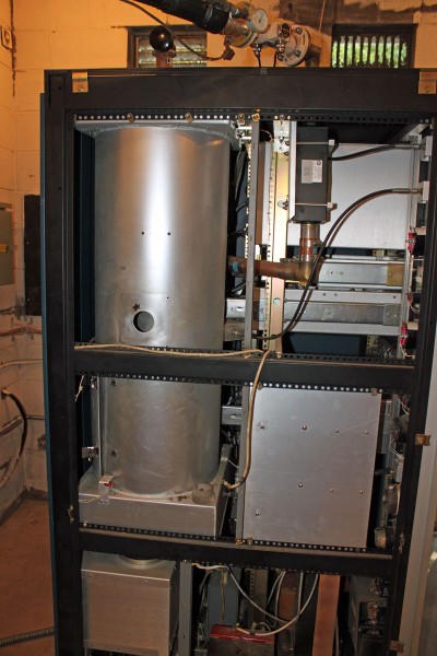
The retrofitting itself was quite the job; drilling six mounting holes and one one-inch feed through hole in the PA cavity, mounting the new feed through housing, rewiring the high voltage connection to the tube and back to the HV bleeder assembly, etc. What with all of the drilling, sawing, filing, deburring, and whatnot, I began to wonder if the transmitter would ever run again. This is the transmitter before the modification:

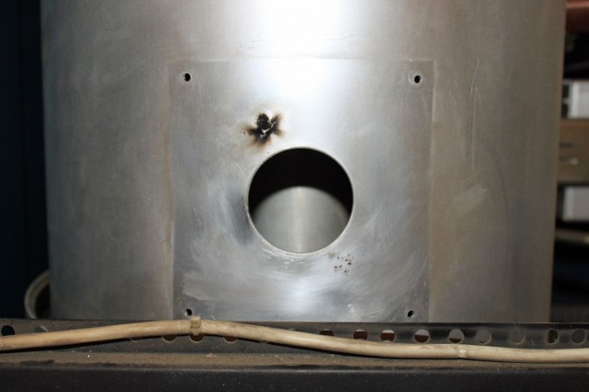
This is the old high voltage feed through hole, arc mark clearly evident.

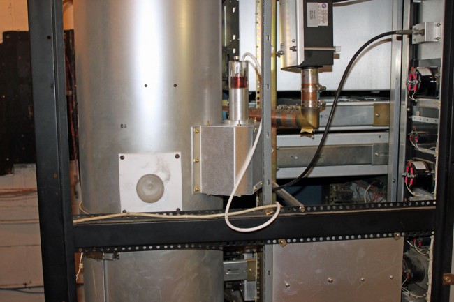
This is the modified feed through/bypass configuration.

While doing this work, I removed the tube and put a plastic sheet in the bottom of the PA cavity and around the HV parts at the bottom of the transmitter. Somehow, getting aluminum filings in the tube socket seemed like a bad idea. I also thoroughly vacuumed out the entire transmitter once all of the metal work was done.
I removed the Kapton capacitor plates from the old feed-through arrangement and reinstalled the Teflon insulating plates to keep the air flow out of the tube cavity going in the correct direction. The new capacitor looks very beefy, perhaps it will never fail again.
Once the installation work was done, I brought up the transmitter first with no screen and no connection to the tube anode. Then with the tube connected, and finally with the screen supply turned on. The tuning needed a brief touch up but all in all, the transmitter came up and ran well with the new feed-through arrangement.
