The Nautel VS-2.5 FM transmitter

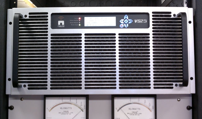
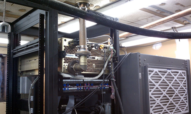
This is cute. A small (VS allegedly stands for “Very Small”) integrated 2,500-watt FM transmitter.  This one we just finished installing as a backup transmitter for WSPK, on Mount Beacon, New York.

Nautel VS-2.5 FM Transmitter

This site has a Nautel V-7.5 as the main transmitter.  That unit is very reliable, however, this transmitter site is non-accessible 4-5 months out of the year due to ice and snow.  The last time we had an off-air emergency due to a crippling ice storm, it took an entire week to clear away all the downed trees so we could gain access to the site via snowmobile.  As such, every system needs dual or even triple redundancy.  The lack of said redundancy has led to several prolonged outages in the past.

WSPK signal flow diagram

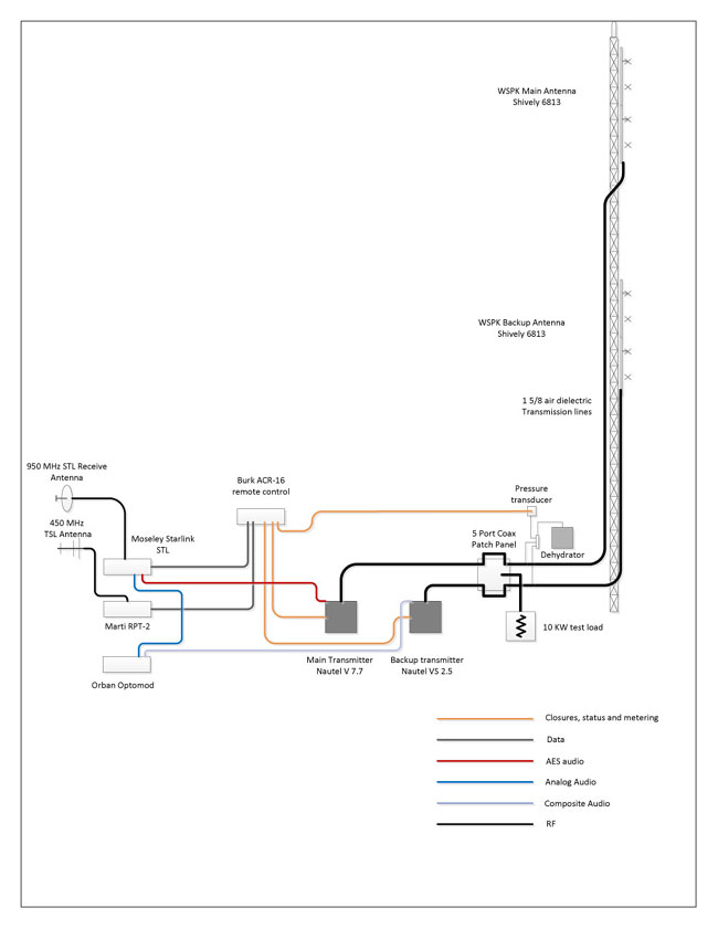
Last year, we were finally able to install a backup antenna after 63 years without one.  This year, it is time to upgrade the rest of the backup equipment.  The new auxiliary transmitter is connected directly to the auxiliary antenna via a five-port coax switch.  This allows for the use of the dummy load for testing when we are present, but removes a potential failure point in the coax switch.  There have been at least two incidences of the disk jockey accidentally transferring the transmitter into the dummy load when taking transmitter readings.  Hopefully, this configuration will be fairly idiot-proof.  I am making an interlock panel that will prevent both transmitters from being on the air at the same time.

Nautel VS 2.5 connections

This site is a work in progress.

The backup processor is at the transmitter site, the main processor is in the rack room at the studio.  This works well because the main processor occasionally looses its mind and needs to be rebooted.  It would be a significant pain to drive all the way up to the transmitter site just to reboot the processor.  It might not happen at all during the winter.  The backup processor has no mind so it is not an issue.

The VS transmitter is attractive because it has a built-in exciter that accepts composite, AES, or IP audio.  The exciter also has a built-in Orban processor as an option.  Thus, if it really hit the fan, we could use the LAN extender to get the audio to the site.  Further, it could be addressed by any studio in the company WAN.  Which is cool, when you think about it.

Nautel continues to crank out innovative, dependable products and there is nothing wrong with that.

The Harris SX 5

I give you joy, the unmitigated joy, and sheer pleasure of the Harris SX 5 AM transmitter. This particular unit dates from 1984 and is installed at WUPE in Pittsfield, MA.   It has a few issues of late.

Harris SX 5 medium frequency AM transmitter

The first of which is the unbalanced or out-of-ratio condition of the PA current and voltage.  When changing power levels, the PA current, and voltage are supposed to track together.  When they do not, it is an almost sure sign that one or several of the MOSFETS in the PA are shorted.  Shorted IRF-350 MOSFETS are indicated by blown fuses on the PA boards and should be replaced in pairs.  The reason for the damaged devices also needs to be investigated.  It is entirely possible that the site receives a lot of lightning, which can cause this damage.  It could also be heat related, as the site is not currently air-conditioned.  The other possibility is under drive conditions.

The MOSFETS turn on and off at a rate of 1/(carrier frequency (hertz)) times per second.  If they are under-driven, they will go full-on and short-circuit.  The minimum drive is 27.5 volts peak to peak, anything less than that is marginal and can lead to the destruction of the PA devices.  Underdrive indicates an issue with the oscillator, which has its own set of peculiar failure modes.

Since this is an older unit, all of the large electrolytic capacitors are also suspect and need to be replaced.  There are three power supply capacitors at the bottom of the transmitter, two 76,000 μF 40 VDC for low voltage and one 7500 μF, 350 VDC for high voltage.  The modulator section also has six 5100 μF 350 VDC capacitors, collectively known as “dynamite sticks” due to their explosive potential if installed incorrectly.

Harris SX 5 modulator section

While replacing the dynamite sticks, I noticed this PDM pickup board has a whole burned through it.  This is a part of the modulator section and if it burned completely open, would likely cause all sorts of problems with this transmitter, likely spurs all around the dial, distorted modulation or perhaps overload and fail altogether.

Harris SX 5 transmitter damaged PDM pull up board
Harris SX 5 transmitter damaged PDM pull-up board

I managed to fix it with a jumper between what is left of the circuit board trace and the capacitor mounting bracket.  I soldered the jumper to the board face and soldered the wire lug.  After scraping all the oxidized metal off of the capacitor mounting bracket, I attached with a screw. The board itself needs to be replaced, if it is still available from Harris, which it may not be as support for this transmitter was dropped in 2008.

Harris SX5 PDM pull up board temporarily repaired with wire jumper

The worst, and I mean worst possible situation with these transmitters is some type of control malfunction.  The control boards and oscillator are in that large vertical pull-out drawer.  God protect and preserve the digital control and S and M boards, as they are a major headache to troubleshoot.  They have 7300 TLL (5-volt logic) that controls all functions and only a little problem will cause the entire transmitter to shut down.

Other SX series transmitter tips can be found here.

I didn’t get to replacing the blown devices because of a looming electrical storm, which precludes working inside of transmitters.  I’ll get back there next week and finish the job.

Update: I finished the repair job today 8/24.  There were 16 blown MOSFETS on the PA boards.  I checked the drive levels on the input side of the RF torrid load resistors and it is with normal range.  I also found this snake in the bottom of the transmitter across the HV shorting bar.

Small grey rat snake, electrocuted by Harris SX 5 transmitter

Could have been chasing diner.  Overall, the site needs help.  The air conditioner is coming next week.

Harris SX 5 transmitter fully operational

After repairs, the transmitter is back at full power and modulating +125% again.

What is this?

Or rather, what is the significance of this:

Wall Graffiti at a transmitter site
Wall graffiti at a transmitter site

A few hints; it was found (written on a wall) at an old, mountain top transmitter site. We are renovating this site and it was underneath an old old alarm panel from the 1970’s that I removed. It reads 468 ÷ 45 = 10.   and the 468 is significant.

Once upon a time, a person could go to the TELCO demark and get all of the inside numbers for the CO and any number of COs in the area.  They would be scribbled on the wall next to the equipment along with many other numbers.   This was especially helpful when doing emergency troubleshooting on a circuit that was down.  Try to do that these days and the most likely result is an unanswered phone.  Most of the smaller COs are not normally manned unless there is a trouble ticket in the process.

Tube transmitters vs Solid State transmitters

I thought it would be interesting to do a comparison between the two types of transmitters, both AM and FM.  I have been doing this thing for 25 years and have quite a bit of experience working on all types of transmitters.  Some of the broadcast transmitters I have personally worked on over the years include:

  • Harris: FM-20H, FM-5G, HT-35, HT-10, HT-3.5, FM-25K, FM-5K, Z5-CD, MW-50A, MW-50B, MW-1A, MW-5A, BC-5H, SX-5, SX-1A, Gates 1
  • Broadcast Electronics: FM-5B, FM 3.5A, FM5A, FM30A, FM35A, FM30T, FM20T, FM10S, FM5C, FM1C, AM10A, AM6A, AM5E, AM1A
  • Continental Electronics: 816R-2, 814R-1
  • Collins Rockwell: 831F-1, 838E-1
  • Nautel: ND-1, ND-5, XL-60, V-40, V-10, V-7.5, NV-40
  • Gates: BC5P, BC1T, FM5B
  • General Electric: BTA-25
  • RCA: FM20ES1, BTA5J, BTA1-AR
  • CSI/CCA, Visual, Energy Onix, Bauer, McMartin, QEI, some Italian something or other, etc.  Various makes and models.

I think I have a fair amount of transmitter experience under my belt.  What I have found is that certain brands of transmitters are better than others, regardless of whether they are tube or solid-state.  There are several differences in each type, obviously.  As to some blanket statement about which is better, solid state or tube, I don’t have one.  My statement would be “It depends.”

Tube transmitters are more rugged and will take more abuse than a solid-state unit. Things like heat, lightning, EMP, and mismatched antenna won’t phase a well-designed, well-manufactured tube transmitter.  On the other hand, they are less efficient AC to RF, have higher B+ voltages, have hard failure modes, and are more difficult to linearize, if that is required for some reason.

Solid state transmitters are more broad-banded, easier to change frequency, they have soft failure mode due to redundant amplifiers and power supplies. The voltages are lower, thus they are safer to work on.

Here is a complete list of advantages and disadvantages of each type:

AttributeTubeSolid StateComment
RuggednessVery rugged, able to take heat, EMP, lightning, mistuned antenna, poor operating environment, etcNot heat tolerant, lightning and EMP can damage MOSFETS, switching power supplies sensitive to AC mains issuesAdvantage: Tube
Electrical EfficiencyLess efficientMore efficientAdvantage: Solid State, however efficiency gain can be wiped out due to larger air conditioning requirement
Failure modeHard, most oftenSoft, most oftenAdvantage: Solid State, failure of a single module or power supply generally will not take unit off the air
Frequency agilityDifficultEasyAdvantage: FM Solid state transmitters can easily be moved.  AM transmitters still require extensive retuning.
Re-occurring costMoreLessAdvantage: Solid State, as tube changes are required every two to three years
MaintenanceSameSameAdvantage: neither
ServicingRequires skilled engineers to service and trouble shootModules and power supplies are often hot swappable and returned to manufacture for repairAdvantage: Solid State, however either type requires occasional measurements with specialized test equipment
Servicing safetyHigh voltages, contact will be fatalLower voltages, but can still be fatalAdvantage: Solid State
RedundancyLowHighAdvantage: Dependant on TPO, Higher powered solid-state transmitters are much more expensive than there tube type counterparts
CostLessMoreAdvantage: Dependant on TPO, Higher powered solid state transmitters are much more expensive than there tube type counterparts
AvailabilityGood used market, some new FM transmitters still being builtGood new and usedAdvantage: Tube
 Reliability Dependent on brand Dependent on brand Advantage: neither

For some reason, the latest Broadcast Electronics tube-type transmitters seem to have very long tube life.  I installed an FM20T at WYJB in Albany, New York,  in early 2001 and it is still on the original tube, some ten years later.  The same can be said for the 2005 FM20T and FM30T installation at WHHZ/WKZY, Gainesville, Florida.   Those tubes show no sign of giving up anytime soon.  I don’t know if that is an unusual trait of the transmitter or that particular tube.

WKZY, Gainesville, Florida

The above comparison seems to heavily favor a solid state transmitter.  As a general rule, brand new solid state transmitters both AM and FM have advantages in almost every category except high power FM transmitters, where tube types still make sense.  From a used transmitter standpoint, there is nothing wrong with a tube type transmitter, provided it has a solid state IPA.  I have noticed the 4CX250B driver tubes most often used in FM IPA stages have markedly reduced reliability of late.  I would also tend away from transmitter makes and models where the manufacture is no longer in business or no longer supports the product.