We have a Harris Z5-CD transmitter for one of our FM stations. Brand H is not my preferred make, however, it was already installed when we bought the station, so I have to live with it.
This particular site gets hit by lightning strikes often. Normally, it does not affect anything until the transmitter gets turned off for maintenance. Then, almost invariably, when turning the transmitter back on one of the modules will fail. Most often this is manifest when one of the two power supplies shut down causing the transmitter to run no more than 20% power.
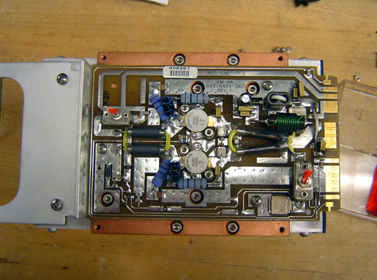
The way this is troubleshot is to slide each module out and turn the transmitter back on. When the power supply stays on, the bad module has been located. A confirmation test is to check the MOSFET for a short circuit between Drain and Source. This short circuit condition puts a direct short on the power supply causing it to crowbar and turn off.
So, once the bad module has been located, and the spare module is installed in the transmitter, then what? Most engineers call Harris and ship the module back for repair. Most engineers don’t want to mess with unsoldering a surface mount MOSFET and soldering a new one in. I find it moderately entertaining to fix things myself, so I do not do what most engineers do.
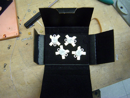
The MOSFET in this particular module is the BLF177, made by NXP. Harris will sell you one for quite a bit of money. You can also buy one from Mouser for about half the cost.
Once the parts are obtained, the worst part of the entire job is unsoldering the old MOSFET. This takes some patience and skill. What I found works best is to melt some solder on the foil leads and get them good and hot. Since this MOSFET is already destroyed, we don’t have to worry about heat, etc. The one thing you do not want to do it actually break the MOSFET open. That is because it contains beryllium oxide, a known carcinogen. Once all the solder is liquid, carefully pry the foil up with a small screwdriver. There are several components that have to be moved to work on this.
After the old MOSFET is removed, clean up the solder pad with a solder pump and solder wick. I like to use a little liquid flux on the solder wick, it makes things go faster.
Once all the old solder is cleaned off the solder pads, I brush a light coat of liquid flux in the pad. Again, this makes things go faster.

The new MOSFETS are very sensitive to static discharge, so I always use a static drain wristband when handling them. I place both MOSFETs onto the circuit board. I then solder them on using as little heat as possible from the soldering iron. Again, the MOSFETs are sensitive to heat and one can easily be destroyed if it gets too hot.

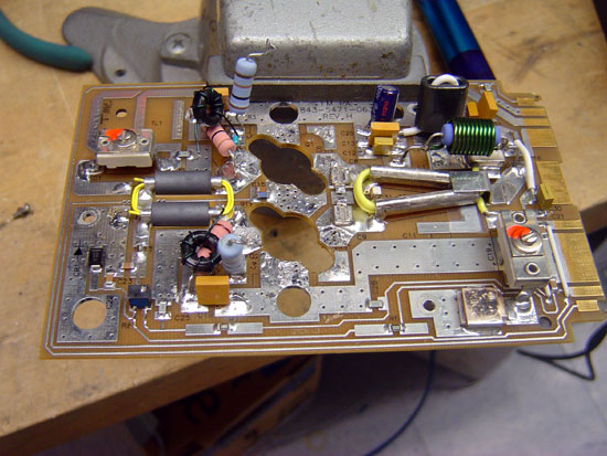
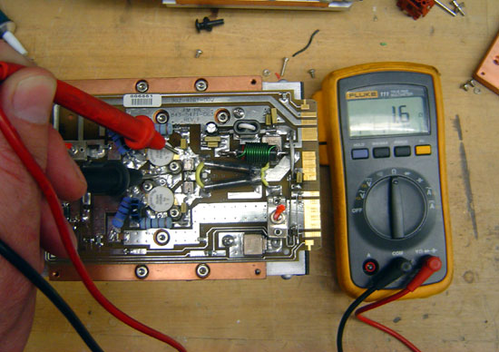
This is the module with the new MOSFETs soldered in. I use defluxing compound to remove all the extra flux. Once it cools off, I test the new module with a DVM:
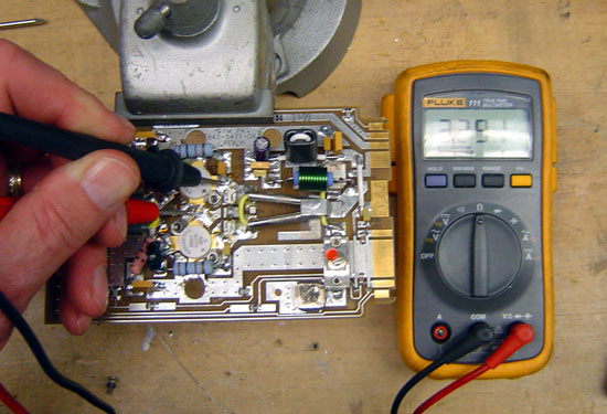
If the MOSFETS are good, they will have an internal resistance of around 3.3 MΩ. If the module is bad the MOSFETS will read only a few ohms if shorted:
That is how you do it. I think Harris charges $775.00 per module to repair. I fixed this one for $240.00, but that is not the reason I did it. I did it for the fun that was in it.

Yes, many the broadcast engineer of today is usually a purchasing agent with a cell-fone constantly in contact with the manufacturer. It is too bad they cannot make strip-line circuit boards with ‘plug-in’ solid state devices. This is why I still like vacuum tubes for high power transmitters. Some will probably laugh, but getting a transmitter back on the air quickly along with good metering made the broadcast engineer’s life a lot easier in the good old days. 833A tubes seemed to last forever before China, and Amperex VHF tubes made in Hicksville, LI were simply excellent! This is why I like running the old stuff. It was built to last whereas the new stuff is built to replace.
Very good work,
many thanks
Josep
hi, i have a transitor BLF177, but it is not delivering the power, I measured the voltage in the drain and in the source, 50v and 3.0v biass, but not operate good, you can help me, I NOT SPEAK VERY WELL ENGLISH
I think you have to first check from the grass-root,it’s good that there is power but i suggest for you to first chenge and fix another mosfet at times they become stuborn if not so check the ceremic capocitor and the around resistor they may be blocking the power.Try your luck
Andrew.Ssewava kkonde
Dear Paul,
is RF Transistor BLF177 equivelent to ON5040,
which is used in harris Z10CD series of transmitter.
inderjit
I don’t rightly know. The BLF-177 part number was from the manual.
the procedure to change the mosfet told by paul thrust is correct . i also adopted the same procedure many time to replace the faulty MOSFET .M an engineer on a fm station in pakistan and i always try to remove the fault in fm transmitter and other equipments my self succesfully. Some time it takes time.
@Javaid, thanks. Keep up the good work. I’ve repaired many of these amps since this was posted, they all seem to work afterwords.
I AM A TRANSMITTER ENGINEER AND MANUFACTURE WITH 5 YEARS EXPERIENCE.I REPAIR ALL TYPES OF TRANSISTORS TRANSMITTER, PALLETS AND MODULES.I CRATE MY OWN PALLETS,MODULES AND TRANSMITERS WITH RDS ENCODER BUILD INSIDE, I AM A GHANAIAN.IN GHANA THE RADIO STATIONS AND TRANSMITTER BUYERS ARE FEW I WANT TO TRAVEL AND WORK WITH ANYBODY WHO IS IN NEED OF A TRANSMITTER ENGINEER NOT IN GHANA.CAN YOU HELP ME? MY email is david14dastech@yahoo.com
@David, sorry I can’t be of more assistance to you. Perhaps one of my intrepid readers will have something more to offer. Good Luck!
please quote me for MOSFET , BLF-177. quantity is 25 pcs.
Also please let me know ,if you can repair the PA Pallet of 425 watts,for Z5 CD Transmitter.
Dear david !
Where are you located please ? In US or elsewhere.
please reply me then I’ll send you my number for contacting me
Lou Arne
To remove the defective MOSFETS / LD-MOSFETS, i prefer to use a hot air gun.
First of all, unsolder the bias coils/resistors from the Drain/Gate leadswith a soldering iron and then,
install the board / pallet on wooden planks (one on the input side the other on the output) making sure the MOSFETS flanges wont touch the planks.
Finally, use the hot air gun to heat the MOSFETS and surrounding board area and using tweezers regularly touch the MOSFETS to see if the solder has molten. If there are drain / gate capacitors, gently take them off when solder melts before you remove the MOSFETS.
This method has the advantage of not damaging the PCB when devices are removed.
However, this method is risky if there are any SS SMD devices close to the MOSFETS as they will fall off when you heat the board. It’s up to you to decide.
And finally, take the habit to take pictures of your board (both sides) before servicing. If a badluck occurs, you’ll have a backup !
Hi Paul ..
Have you ever tried to fire up one of these PA modules on the bench? I’m curious to know if you had any troubles feeding an input signal in the module…
Hello Paul,
Just replace the mosfet damaged by a similar ON5040.
I have done a test outside the transmitter. my question is how do to inject the gate voltage, and this voltage can simulate.
Thank you
Hey Luis, I usually use a volt ohm meter, you can bias the gate on or off with the positve lead.
Thank you Paul, for you info.
Regards
hola , estoy buscando 2 transitores mosfet
para un harris transmitter 6, 000 watts
thanks
alfredo
wakb 94.3 fm
I need 2 mosfet transitor for z-5 fm trasmiter harris…thanks….I need help
I am a programs manager to a radio station in the Upper west Region in Ghana and need someone who deals or repair radio transmitters should please contact me on the Email: (redacted)
ed note: contact blog admin if you want to help this guy
sir i havetaken for repair and replaced but i am getting high output what is the problem
I need to replace the mosfets on this harris pallet srf 4245 where can I get these
Good Morning,
Here in New Zealand,pallets for nay type of VHF amplifier are like gold, and when I saw this one i quicky purchased it.
Is it possible to send me a schematic of the amp , mine has the on5040 devices in it,
secondly have you ever tried to move it up to 144 mhz
I am hoping you receive this, and can help
Thanks Ross
Paul, when you repair these boards and put back in the transmitter, do you notice any increase in ISO LOAD temps? The factory phases these (note trimmer caps on the board).
Having never worked on Z transmitters before, I’ve recently had the pleasure of working on a very early version of this beast. It started out very strange because someone had stuffed Z3.5 firmware into it, so four of the PA pallets were invisible to the Master Controller. This unit has the -001 PAs with the Motorola MOSFETS. GatesAir cautions not to mix -001 PA’s with the newer PA modules in the same PA deck. We had a bad PA module and elected to make a module exchange. Turned out the exchange module was the newer design, and the ISO temp skyrocketed to 100 in a few minutes. That module ended up in the IPA, where it lives happily in isolation.
The factory also advised that a common failure of the -001 modules is fatigue cracking of the solder holding down the tubes of the transformer loops. If the tube becomes detached, MOSFETS’s will blow.
Hal, that is a good question. Last week, I went to several transmitter sites where these repaired modules have been installed. No major differences in ISO load temps that I could see.
I actually own a Z5 that I use as a rental from time to time. De-soldering the Mosfets is a real pain in the head. I use a razor blade to cut all the tabs, then a remove the heat sink and the tabs slide off easily. Thanks for the article!
Could you Pm me a copy of the circuit,I have searched the web and cannot find a copy
Thanks Ross
I have about 15 of these harris amplifier boards for sale. used. contact me at: (redacted)
Contact blog owner for email info
After replacements of these faulty MOSFET,s need to tuning ? or it will work properly?
Paul, I have a PA board from a Japanese 1KW amplifier that uses (4) VRF 2933 Mosfets. Could I send it to you for repair since I lack the ability to do it myself? We took a hard hit here from Hurricane Maria and supplies and equipment are very limited.
Herb Schoenbohm
Box 24261
Christiansted, VI 00824
Paul,
Have you had to order any BLF177’s since they went EOL? Mouser no longer has them, but I see RF Parts still lists them, and there’s a bunch on eBay (buyer beware). I just had to order IRF350’s from an eBay source for an SX-1, and that doesn’t feel good, even though I realize the SX is chock-full of other unobtainium parts.
Gregg, I have not had to order BLF-177s in quite some time, I think we still have a pallet or two in stock. This is one of the problems with solid state devices, they have a finite production life, after which the supply runs out and the equipment design becomes obsolete. All of these solid state transmitters have a life expectancy of about 10-15 years unless a very good spare parts stock is maintained.
Hi
I’m try to find ON5040, I need 6 units.
Could you quote me price?
Regards
Nguyen Viet Bang
When Harris changed those modules to work with IBOC, we ended up with dozens of them that we couldn’t use. Many years later, I took them apart to salvage the copper. I got good at tearing them apart, never thought about repairing them.
All the boards and devices went to the e-waste pile. I kept 2. I have since used them as IPAs. The same module was also in the early Z series IPA and beta IBOC parts.
I have a Harris chassis that is essentially a power supply and edge connector with a module, and fan. They are easy to turn in to a PA in a pinch.
Hello Mike:
My name is Don Parker
With WLJN radio in Traverse City
Mi. Do you still have any more
PA pallets for the Harris z series
Tx ? Thanks for any information . Don Parker
donp.@wljn.com
I tried every thing ,the rf finals boards all seem ok but the trans wouldn’t go up past 6.75% I did remove and replaced all the control boards and left unplugged the #3 board I missed and the power went up to 10% with out shutting down ,replaced and it fell to 6.75 again so I left the #3 board unplugged witch got me up to 14% now while not fixed its a lot more power than I had
@allen branch:
Call GatesAir support. If Walter Freeman is still there, he can help.
Hello!
How can I repair the power supply of a Harris zx500 transmitter, please?
Here is my whatsapp number: (Redacted)
Ed Note: Try contacting GatesAir. They have an excellent service department: support@gatesair.com
Would this work to test for a bad MOSFETS? If the PA is still in one piece?
If I read 2.2 ohm on a PA is it considered bad?
Mark, take a clip lead or something, connect one end to a good ground then use the other end to ground all of the leads on the MOSFET. Then measure. Depending on the ohm meter, you should see an open or something in the 2-3 Megaohm range. If it reads 2.2 ohms, then the MOSFET is shorted and needs to be replaced.