The curious case of the WKZE Notice Of Violation

On June 19th, WKZE received a notice of violation from the FCC’s New York Field office.  The crux of the issue seems to be interference being generated on 784.8 MHz (WKZE 8th harmonic) to a new Verizon Wireless installation located nearby:

47 C.F.R. §73.317(a): “FM broadcast stations employing transmitters authorized after January 1, 1960, must maintain the bandwidth occupied by their emissions in accordance with the specification detailed below. FM broadcast stations employing transmitters installed or type accepted before January 1, 1960, must achieve the highest degree of compliance with these specifications practicable with their existing equipment. In either case, should harmful interference to other authorized stations occur, the licensee shall correct the problem promptly or cease operation.” The eighth harmonic of Station WKZE-FM (784.8 MHz) was causing interference to the Verizon Wireless transmitter located approximately 500 feet away.

First off, we note that the WKZE transmitter is not allegedly causing interference to a Verizon Wireless transmitter, but rather to a Verizon Wireless receiver.  That may be splitting hairs, however, since the FCC is quoting a technical rules violation, they can at least get the technical language right.

A brief examination of the rest of FCC part 73.317 is in order to find the specification cited in section (a).  Section (d) states:

 (d) Any emission appearing on a frequency removed from the carrier by more than 600 kHz must be attenuated at least 43 + 10 Log10 (Power, in watts) dB below the level of the unmodulated carrier, or 80 dB, whichever is the lesser attenuation.

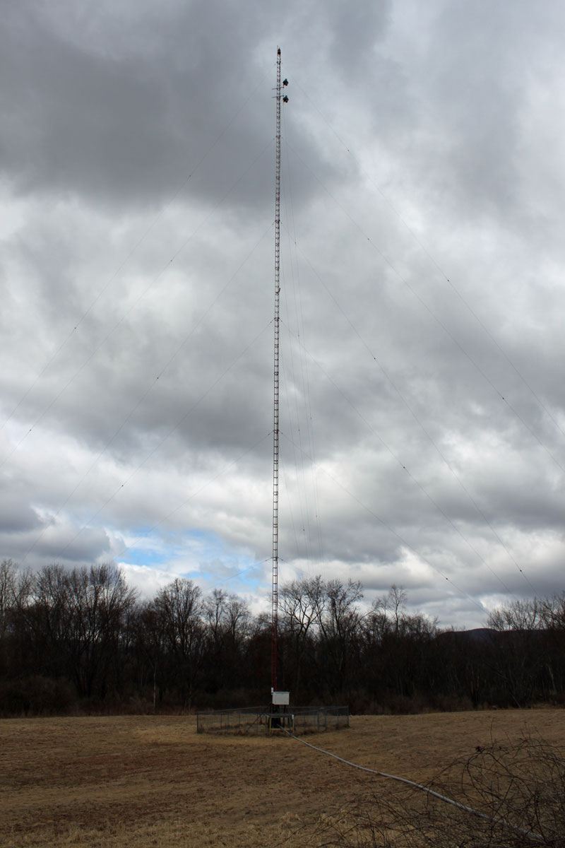
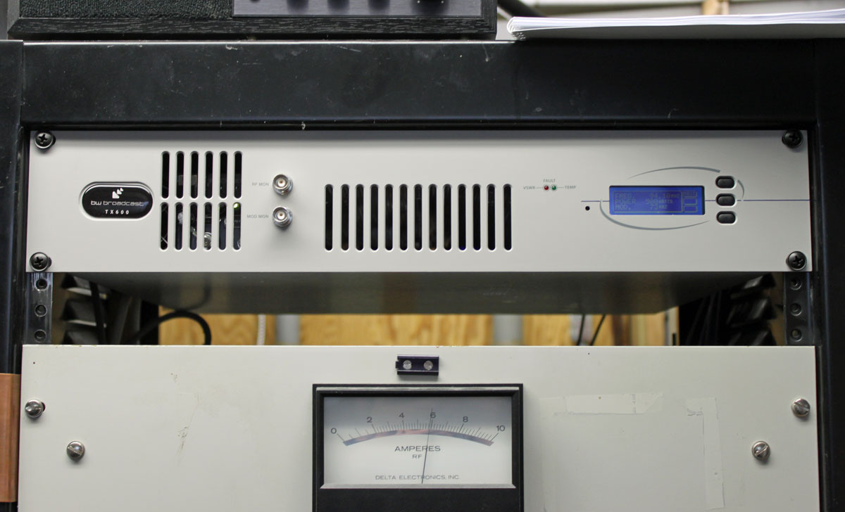
Since 784.8 MHz – 98.1 MHz is greater than 600 KHz, this is the section that applies to the WKZE situation.  Thus, the interfering signal must be greater than -80 dBc to trigger the Notice Of Violation (NOV) from the FCC.  The station ERP is 1,800 watts or +62 dBm.  Measurements were made with an Agilent N992A spectrum analyzer using an LPA-1000 log periodic antenna.  At a 12-foot distance away from the WKZE transmitter cabinet, the signal on 784.8 MHz was found to be -94 dBc or 0.000063 watts.  At the base of the Verizon Wireless tower, the measurement was -124 dBc, or 0.000000025 watt, which is barely perceptible above the -130 dBm noise floor.  There does not appear to be any violation of 47 CFR 73.317.  Rather, the issue seems to be Verizon Wireless’s deployment of the 700 MHz LTE band and the use of high-gain antennas coupled with high-gain preamplifiers on frequencies that are harmonically related to broadcast stations nearby.  In this particular installation, the antenna has 16 dB of gain, minus a 4.5 dB of transmission line loss into a 21 dB preamplifier before the receiver.  At the output of the Verizon preamplifier, the signal on 784.8 MHz was measured at -89 dBc, which is still in compliance.

By these measurements, clearly, WKZE is not in violation of any FCC regulation.  It makes one wonder, does the FCC understand its own rules?  Or, is this a matter of favoritism towards a huge corporation over a small independent radio broadcaster?  Is it a matter of “broadband at the expense of all others?”  There are several of these broadcast to 700 MHZ LTE interference cases pending throughout the country.  This could set a dangerous precedent for broadcasters and other RF spectrum users as wireless giants like Verizon throw their weight around and eye even more spectrum to press into broadband service.

Commlaw blog has a good post on this subject: Harmonic Convergence?

Update: The response from the WKZE attorney can be found here, including the above-mentioned actual measurements.

The Shively Branched combiner

Did some work a while ago at a transmitter site that had three transmitters combined into one antenna.  The site uses a Shively branched combiner:

Shively Branched combiner

Each transmitter can be tested into a separate 20 KW dummy load:

Three inch coax switches

Transmitter themselves are Nautel NV15s:

Nautel NV20 transmiters
Nautel NV15 transmiters

Except for the one on end, which is an older BE FM20A.

Well designed circuit boards

Sometimes it is the little things that catch the eye.  When I was installing a Nautel transmitter recently, I was admiring the circuit boards used for the transmitter controller.  I have seen a few circuit boards that are functional, but leave a little to be desired in the form department.  Does it really matter?  Perhaps not, but often times those tiny, almost insignificant details come back to bite you.  Little things like having the voltage regulator pins correctly placed or putting a toggle switch on the correct side of the board.  I have seen both mistakes from another, well known transmitter manufacturer.

Nautel NV controller board

Anyway, these are a few photographs of some well designed, well laid out circuit boards.

Controller board, NV transmitter

This is the main controller board.

NV controller board surface mount components

Surface mount components.

NV controller board
NV controller board

Logic chips.

Nautel XR harmonic filter, part back part is the circuit board

Part of the harmonic trap for the XR series transmitters.

It really is the little things that make big differences.  A circuit board under a cover that few people will ever see may seem like a very small and insignificant detail, but I notice and admire these things…

Moving and upgrading a translator

Something that I eluded to in a previous post, we finalized the move of the WSBS translator, W231AK, from the Fairview Hospital in Great Barrington to the side of the AM tower.

Tower crew hanging translator antenna on AM tower

The move was started by hanging a new Shively 6812B antenna from the side of the AM tower, located off of US 7, north of Great Barrington. This is a half-wave-spaced circularly polarized antenna.

While this work was going on, some guy from OSHA showed up and started taking pictures without asking permission or telling anyone who he was.  We informed him that he was on private property and asked him his reasons for being there.  He got in his car and left, no doubt to a parking lot down the road so he could keep the tower climbers safe… mostly from themselves… by levying huge fines for free climbing…  Wasn’t there something in the news about the government running out of money?  Anyway…

W231AK antenna, Great Barrington, MA

WSBS had been using this translator for a few years. The advantages for the station from the translator move are greater power output (from 35 watts to 250 watts ERP) and less operating expenses in the form of TELCO line charges and roof top rental at the Hospital.

WSBS tower with W231AK antenna mounted

In addition to that, the reliability of the translator should increase, as there have been several instances in the past when TELCO line problems have taken the translator off the air for days at a time.

W231AK new transmitter
W231AK new transmitter, WSBS base current meter below

The transmitter for W231AK was changed from a Crown 35 watt unit to a BW Broadcast T600.  These units are made in the UK and it is an all-in-one processor/exciter/transmitter. We took the cover off to make a few configuration changes and the entire unit is very well made.

BW Broadcast T600 insides

One of the nice features of this particular transmitter is the screw-down clamping method of connecting the RF devices. Lets face it, unsoldering MOSFETS is a PITA. This screw down clamp eliminates all that.

BW Broadcast T600 power amp

The audio input and processing board is pretty neat too.

BW Broadcast T600 audio input board

There are several different processing settings which we played around with.  All in all, it seems like a pretty solid unit and I would recommend it to anyone looking for a low to moderate power transmitter.