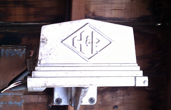
This is a Hughey Phillips mechanical tower light flasher that has been in service since 1960. Basically, it is a motor connected to a cam that rocks a mercury relay back and forth. These were standard technology for tower lights from the 1930s through about 1970 or a little later. They were very reliable, we still have some with a “pancake motor” in use on some of our towers. They were very robust and immune to lightning damage, RF interference, and other problems. The only maintenance that I can think of is lubricating the motor bearings. Eventually, however, they do wear out. Cold weather seems to take its toll, often causing the motor to stop.
Hughey and Phillips mechanical tower light flasher
This particular unit is mounted inside the tuning house for the far tower (north tower) at the WGHQ antenna array. It has finally reached the end of it’s existence; the motor bearings are shot and it has gotten stuck in both the on and off position this year causing the FAA to be notified of the malfunction.
WGHQ 920 Khz Kingston, NY antenna array
Today, I am replacing it with a solid-state flasher (SSAC B-KON FS155-30RF). Solid-state flasher units have been known to malfunction in high RF fields, such as AM towers. To cure that, the manufacturer has built-in 0.01 uf bypass capacitors, hence the “RF” suffix. Older units did not have built-in bypass caps, so external 0.1 uf bypass capacitors were normally installed on units mounted to AM towers. While I was working on this, I turned the transmitter down to 500 watts, no need to get any RF burns.
Naturally, this has to happen after there is two feet of snow on the ground. Also, it should be noted that this is the furthest tower away from the transmitter building. Now where did I put those snow shoes? Never mind, it has been very cold and the ground is frozen solid, I’ll take the truck… This is good because I will have all the tools, drills, nuts, and bolts without having to walk back and forth several times in the snow.
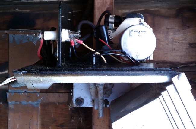
Hughey Phillips mechanical beacon flasher
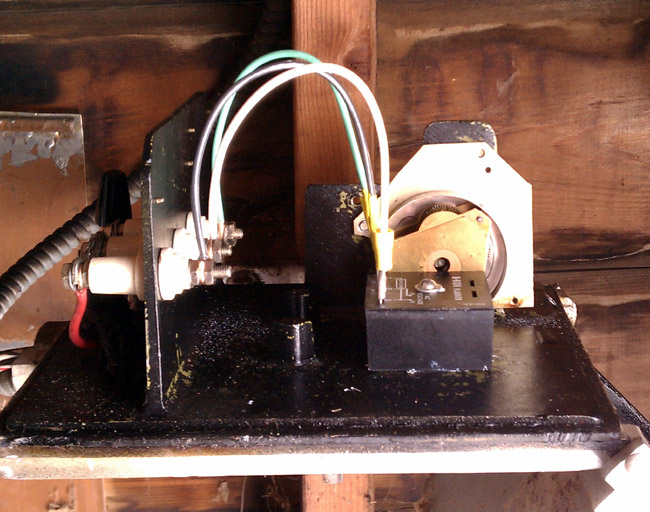
I removed the motor and mercury-filled relay. I’ll have to figure out how to dispose of the relay. I then drilled a mounting hole through the base of the old flasher housing and bolted the solid-state relay to it. This is required because the solid-state relay needs a pretty good heat sink.
SSAC B-KON tower light flasher
Turn everything back on and: Ta-da! All works normally, the tower beacon is flashing away up there. Time to leave.
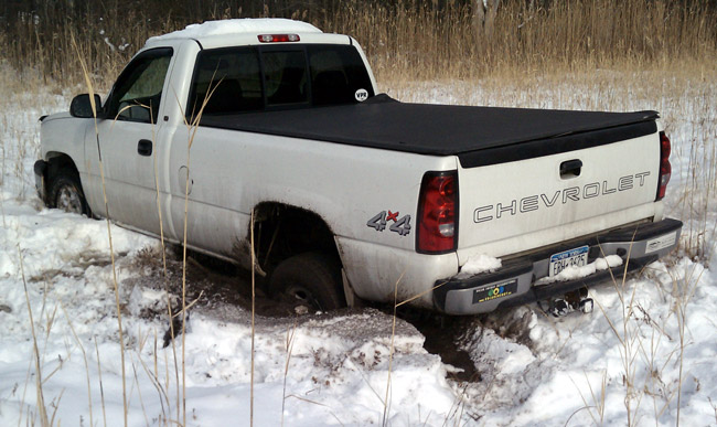
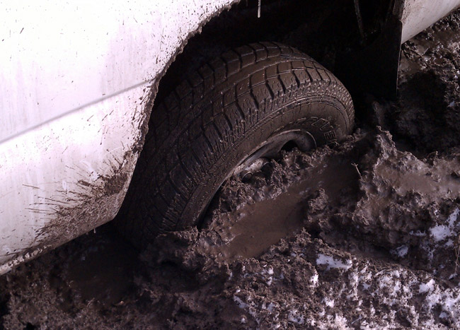
Truck stuck in swamp
Pull forward about 2 feet to turn around and CRUNCH! The truck goes through the ice of a hidden stream. Any attempt to move only makes it worse:
Truck rear burried to axle
Put in a phone call to the one guy I know that can get me out. About an hour later he shows up with chains, a shovel, and a come-a-long. We attach the come-a-long to the fence support post and pull the truck out backward 1/2 inch at a time. It took us about an hour and a half to get it all the way out so I could drive it back across the field. I’d have taken some pictures, but my guy; was a little grumpy.
I won’t do that again.
Still, I did the job I came to do, so it was a good day after all.
Another one of those things that might work could possibly provide some service to travelers, but often falls short. Very similar to EAS, the government officials nominally in charge of the system have no idea of broadcasting. The Rhode Island TIS on I-95 had an endless loop proclaiming “This is the Rhode Island Department of Transportation Travelers Information System.” While that was welcome information, in a snowstorm, something about road conditions or perhaps the weather forecast might have been more appreciated. According to the FCC website, that was WPTJ441 on 1630 KHz with a power of 10 watts. The transmitter is located at the I-95 rest area on the Rhode Island/Connecticut state border.
The FCC is seeking comments on the current TIS in NPRM 10-203:
We solicit comment on whether to modify the existing rules governing the licensing and operation of Travelers’ Information Stations (TIS) to expand the scope of permitted operations. Since the inception of TIS in 1977, the Commission has authorized TIS operations to permit Public Safety Pool eligible entities to transmit noncommercial travel-related information to motorists on a localized basis. However, certain parties and licensees have sought to expand the scope of TIS operations in order to transmit more general alerts and public safety-related information to the public, including non-motorists. By initiating this proceeding, we grant petitions for rulemaking filed by Highway Information Systems, Inc. (HIS) and the American Associations of State Highway and Transportation Officials (AASHTO) requesting the commencement of a proceeding to amend the TIS rules. We deny the petition for declaratory ruling regarding TIS filed by the American Association of Information Radio Operators (AAIRO), but incorporate the issues raised in AAIRO’s petition into this rulemaking proceeding
The TIS as specified in the 1977 RO docket 20509 FCC 77-414 is outdated for the most part. The current rules, 47 CFR 90.242 give pretty specific requirements including things TIS stations are not allowed to retransmit, like NOAA weather forecasts. In one section of the NPRM, it is noted with the currently specified facilities, the average vehicle traveling the speed limit will transit the TIS coverage area in 90 to 120 seconds. For the above station, I found it was listenable for about 5 minutes, from the time I saw the sign next to the transmitter until it faded out, which works out to be about five and a half miles.
One alternate possibility is something like a carrier current station or a leaky coax setup buried in the median. Something like that might have more reliable coverage along the highway without blanketing the general area with a broadcast signal.
Again, in Rhode Island, drivers have the option of calling 511 on their cellphone, provided it is a hands-free cellphone. My only comment about that is when there is a major traffic jam and everyone is dialing 511 to get information, the cellular network will get congested quickly. Having a broadcast outlet for people to listen to on their car radios would be a more effective way to transmit information to the masses. As to what information a driver might want; here are a few suggestions:
Up-to-date traffic information including alternate routing instructions in case of a major tie-up.
Up-to-date weather information including roadway surface conditions and possible lodging locations
Up-to-date construction project information including alternate routing instructions for both car and truck traffic
When there are no traveling issues, other general information about rest stops, hospitals, tourist attractions, etc.
The most important thing is the information is up to date and relevant to a traveler.
At the place of my former employment, there is an issue with AM reception. The building is full of old, electrically noisy fluorescent light ballasts, computers, mercury vapor parking lot lights, and every other electrical noise generator under the sun. The second issue is that one of the EAS monitor assignments for two FM class B stations is WABC in NYC. Under normal conditions, WABC puts a fine signal into the area. Listening to it is not a problem at my house, in the car, and whatnot. However, at the studio, the station is audible but terribly noisy. Every time one of those FM stations ran a required monthly EAS test originating from WABC, it was full of static and just sounded bad on the air.
The state EAS folks were inflexible as to the monitoring assignment. “WABC is the PEP station for NY. You should have plenty of signal from WABC at your location,” said they.
At one time, the studio had an active loop antenna (LP-1A) from Belar, which worked but also seemed to amplify the noise. I decided that the best thing to do was go big and ditch the preamp. I made a diamond-shaped receiving loop on two pieces of two-by-four by eight-foot lumber. I wound four turns of #14 stranded wire around this frame and made a 4:1 balun to feed the unbalanced 75-ohm RG-6 coax.
That cured the noise problems and for eight years, WABC sounded pretty good on the EAS monitor.
Fast forward to about a week ago. The roof at the studio building was being redone and all the monitor antennas had to be removed from the roof. The homemade loop was not in good shape. The balun box was full of water, the lumber was cracking and falling apart, the insulation was degraded by UV exposure, etc. My boss asked, “How much to make a new one?” So I said something like forty dollars and a couple of hours. He then said, “Make it so we don’t have to ever make another one.”
Music to my ears. I started by checking my assumptions. I made a model and ran NEC to see what the electrical characteristics for that size loop were on 770 KHz. It came out better than I thought, with about 1-ohm resistance and 282 ohms inductive reactance. Fooling around a little more showed that roughly 1.3 uH inductance and 720 pF capacitance in an L network would bring this in line for a 50-ohm feed point. Since this is a receive-only antenna, that is not a prime consideration. I am more concerned with noise reduction and maintaining at least the bi-directional quality of a loop antenna.
NEC 2 model AM receive loop
Then, I decided to get fancy. What if the capacitance was put on the end of the loop to ground instead of the feed point? That, in effect, should make the loop directional off of the unterminated side. Driving the feed point with a 9:1 balun would also bring up the inductance on the feed point. Finally, grounding the whole thing with a separate ground lead might also get rid of some noise.
The final configuration looks something like this, which is essentially a top-loaded vertical:
Low noise AM loop antenna
Now to build it.
Once again, I felt that a non-conductive support was needed, so I used two by four by eight-foot lumber, but this time I painted them with oil-based paint. The side length worked out to be 5.7 feet per side, or 23 feet per turn for a total of 92 feet of wire.
I purchased 100 feet of PV (photovoltaic) wire (Alpha wire PV-1400), which is UV, heat, and moisture resistant and designed to last for 30 years in outdoor, exposed environments.
For the balun box, I used a metal outdoor electrical box with a metal cover. I put a ground wire jumper between the box cover and the ground common to maintain shielding. I used a water-tight bushing to feed the antenna wires and the ground wire into the box. I drilled a 3/8 hole for a type F chassis connector. Everything was given a little extra waterproofing with some silicone-based (RTV) sealant on all threaded junctions.
The spreaders for the wire windings are UV-resistant 1-inch PVC conduit. I drilled four holes, three inches apart in each spreader to run the loop wires through.
The balun is 7 trifiler turn of 24 AWG copper wire on an FT-43-102 toroid core. Trifiler means three wires twisted together before winding the toroid core.
I used all stainless steel screws and mounting hardware.
The loop is terminated with a 500 pF, 500-volt ceramic capacitor to ground. Once in place, I am going to experiment with this by jumping it out of the circuit to see what effect it has on noise and signal strength. I may also try replacing it with a 200-ohm resistor and or a 1000 pF capacitor.
The assembly was pretty easy, although time-consuming. My four-year-old son helped me paint the wood and string the wires through the spreaders.
I soldered all wire connections with 5% silver-bearing solder.
When the whole thing was assembled, I tested it out with my Drake R8 receiver. It performs much as expected, with low noise, directional away from the terminated wire loop. It does not appear to be too narrow-banded either, as the stations on the high end of the dial were also received with good signal strength.
Next was loading it on the pickup truck, driving it in, and mounting it on the studio building. I got some funny looks from my fellow travelers, then again, I usually do.
For the ground, I purchased an eight-foot copper-clad grounding rod and pounded it into the ground at the corner of the building. This area is always wet as it is the lowest area around the building and all the gutters drain there. This is not best RF ground, but for the purposes of this antenna, it should work fine. I used about 28 feet of leftover #12 stranded wire from the ground rod up to the balun box and connected it to the common ground point inside the box.
The frame itself is mounted on a standard wall-mount antenna pole. Stainless steel clamps hold the wood frame to the pole.
Once it was installed, I used my Kenwood R-2000 receiver to find the best mounting azimuth and locked everything down. I also put a toroid on the RG-6 coax coming up from the rack room to keep any shield noise from getting into the antenna.
AM receive loop PVC wire spacers
AM receive loop wood frame
AM receive loop balun transformer
The tuning capacitor is in there too, behind one of the loop wires.
AM loop antenna installed on roof
Antenna installed. I did try substituting the 500 pF capacitor with a 220 resistor. The signal strength came up somewhat, but the noise increased more, therefore the capacitor is a good termination for this antenna.
With this antenna, the signal from WABC is nice and clean and sounds good on the FM station when a monthly EAS test is retransmitted.
I have received an e-mail from occasional reader John, who comments that many of the Windy City AMs have turned their buzz saws off. I note today, that the same can be said for many of the NYC AMs. WABC has had its IBOC turned off for quite some time. The latest to turn off is WNYC on 820 KHz. Several people have noted the loss of noise on their signal this morning.
According to Ibiquity’s own website, only six AM stations in the NYC market are currently using IBOC.
What does this mean?
Could it be that management is finally realizing that the cure is worse than the disease? The disease is alleged poor audio quality, and the cure is IBOC itself.