I received this link in the comments of a previous post and found it interesting. The BBC will be closing down 648 KHz, Ordfordness England at the end of March, no doubt due to budget cuts. The site has been in use since 1972. Prior to this, the site was formerly an OTH array, COBRA MIST, which was then adopted for MW broadcasting. The video is 17 minutes long, but, if you are interested in radio history, technical aspects of AM broadcasting, and the like, it is interesting.
These are 600 KW transmitters. As Andy Matheson, transmitter engineer, explains, with a wry smile “I find them (transmitters) very satisfying, I enjoy either day work or shift work, just really working with transmitters has always been very satisfying…” I couldn’t have said it better myself.
Amplitude Modulation (AKA AM) was the first modulation type to impress audio on an RF carrier. Prior to this, information was transmitted via on/off keying of a continuous wave transmitter using Morse code or some equivalent.
There are several methods for generating AM in a transmitter.
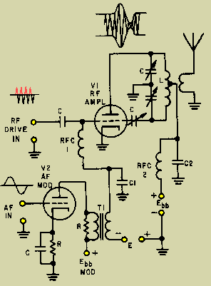
1. Low-level modulation. The modulation is developed in the first stage RF section, then amplified by subsequent stages to full power. Simple and easy to implement, especially for mobile transmitters and SSB installations. Disadvantages come from the need for linear amplification through all the stages requiring class A or AB amplifiers and do not reproduce wide band AM well.
Grid Modulated AM transmitter
2. Doherty modulation. William Doherty came up with an ingenious way to use a low-level linear modulator with good to excellent efficiency. Under full carrier, no modulation conditions, the carrier tube is generating the RF carrier, and the peak tube is mostly cut off (very little current). When modulation is applied, the peak tube then begins to conduct, the output of this tube is combined with the output of the carrier tube through a 90° LC network, which is the same as a 1/4 wavelength transmission line. The effect of this is to lower the output impedance, thus allowing the carrier tube to modulate 100 percent.
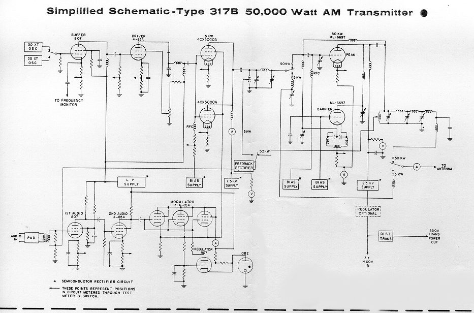
Later, Continental Electronics and Jim Weldon somewhat modified this system in their 317C series high-power transmitters.
Continental 317B simplified schematic diagram
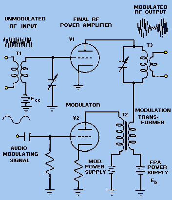
3. High level or plate modulation. The RF and Audio sections are developed separately within the transmitter, then combined in the final stage of the transmitter. Older systems used a modulation transformer. The advantages are all the amplifiers can be run class C or greater, which reduced electrical consumption and power supply requirements. Much higher power levels are achievable with this design. These transmitters also reproduce wide-band audio much better than low-level modulated units. They are also extremely rugged. Disadvantages are the system requires large audio sections and they take up a greater area and are not as efficient as later modulation methods.
Plate Modulated AM transmitter
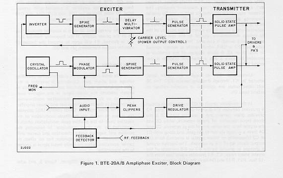
4. Ampliphase. A phase-modulated system developed by RCA where the transmitter developed two RF signals in the final, 135 degrees apart. To modulate the signal, the phase relationship between the carriers is varied, more toward 180 degrees would be a negative peak, and more toward 90 degrees a positive peak. These transmitters required less space and were more efficient than traditional plate-modulated transmitters. They required careful setup and tune-up to reduce distortion and somewhat unfairly earned the name “amplifuzz” from some engineers.
RCA BTE 20 ampliphase AM excit
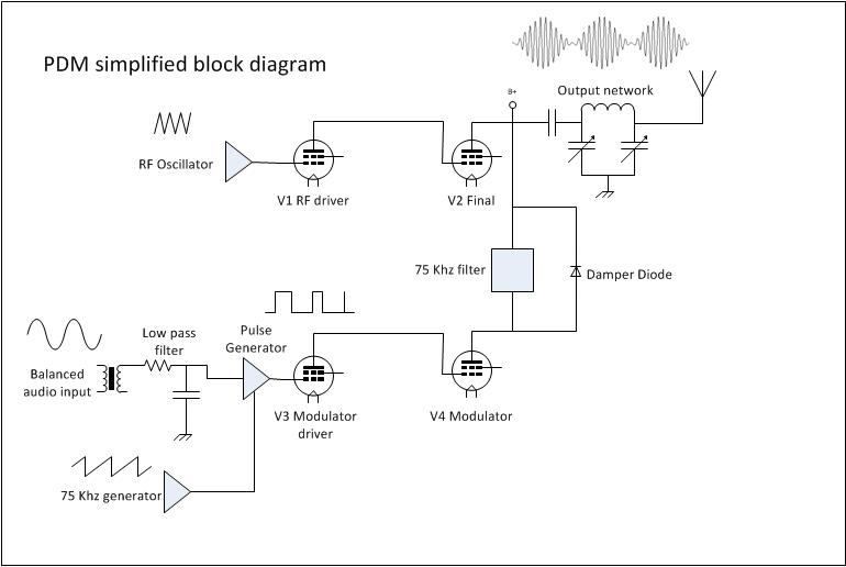
5. PDM or PWM. This is also a high-level modulation scheme but with some slight variations. The carrier power level and modulation levels are set by a PDM encoder card. In Harris transmitters, the PDM frequency was 75 KHz. The carrier is set by the amplitude of the PDM waveform, and the modulation is determined by the duration of the pulse. PDM transmitters require power supply voltages about twice the voltage of a standard high-level plate-modulated transmitter. They also require a damper diode to conduct the B+ voltage to back to the power supply during negative peaks, otherwise, the PA voltage will attempt to rise to infinity. I have found the damper diode to be the weak link in a tube-type PDM transmitter.
Solid state transmitters also use this design with either MOSFETs or BJT, which are then combined in parallel to generate the required output power. This is most often called “Class E” or something similar. In that system, each pair of modulator MOSFETs has its own fast-acting damper diode, usually protected by a fuse.
Harris MWx tube type PDM transmitter
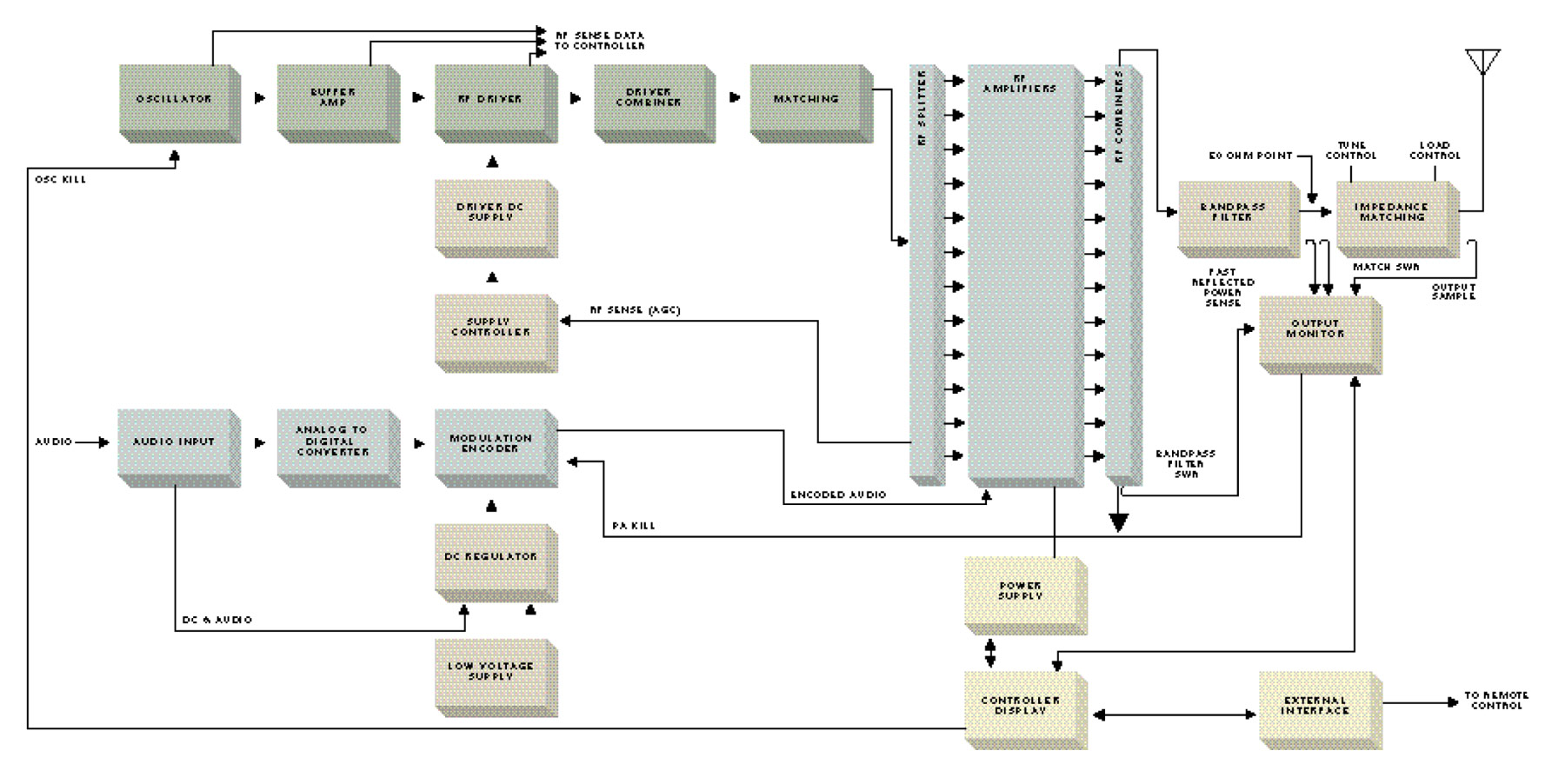
6. Direct Digital Synthesis. This is a patented design from Harris Broadcast used in their DX series transmitters. The incoming audio is sampled at either the carrier frequency or 1/2 the carrier frequency depending on where in the band the station falls. The solid-state PA modules are then switched on and off at the carrier frequency with the audio levels imposed on the carrier information. The explanation is simple, the application is complex:
Harris DX series AM transmitter block diagram
Of all these transmitters, the Harris DX series is the most efficient from a power input (AC) to power output (RF) perspective. There are several methods of reducing electrical use by reducing carrier power levels during lulls in modulation. The Continental 418E and later series transmitters can reduce carriers up to 6 dB using CCM. Harris and Nautel use similar systems on their DX and XL transmitters respectively. The wheatstone corporate blog has an article: Greener AM transmission Methods that details others.
As far as simplicity, serviceability, and rugged design, the high-level plate modulated transmitters cannot be beaten. Many Amateur Radio operators build these units from scratch using old parts, tubes, and other reused equipment readily available, often for free. I have, in fact, donated several 1 KW AM transmitters to ham radio operators over the years.
If I were to design a “transmitter of last resort,” to use in case everything else fails, it would look something like this:
813 Tube type 250 watt transmitter final813 Tube type AM transmitter modulator section
The disadvantage of that design is it requires a 2KV power supply, which has its own set of safety concerns. I might substitute 833s for 813s and use heavier iron in the modulation transformer. That way the transmitter could develop a 500 to 1,000-watt carrier. The great thing about tube transmitters is, given the right output components, they can be tuned into almost any load. They are also easily adaptable for emergency operation into temporary antennas.
Looks like the AM HD Radio™ juggernaut continues… To sink under its own technical faults that is. According to the list the number of AM stations running IBOC in the US is now down to 233 stations from a high water mark of 290 or so. That represents a total of just 4.8% (233 IBOC/4782 Total stations) of all US AM radio stations. On a related note, Bob Savage of WYSL 1040, Rochester, NY has a good idea:
I’ve always said – if you want to see surprising new life in the AM band, s**t-can the stupid irrelevant NRSC pre-emphasis filter and allow stations to run to 15 kHz during daylight hours and 10 kHz nighttime. Mandate C-QUAM in all receiver and receiver devices.
It will sound better than HD, be more robust, and cause far fewer problems. Plus it wouldn’t obsolete a single radio out there, while making a whole bunch of them sound a whole bunch better.
It is so simple in concept, so easy to implement, with almost no expense to AM stations. Again, Mr. Savage:
Most software-based processors have com ports which can be addressed by a remote control system like Sine Systems, so when the power gets reduced at evening pattern change, the bandpass can be changed at the same time…..vice-versa at sunup. No biggie.
For older setups a simple outboard relay and rolloff network could accomplish the same thing. It’s a little more complex but again, not a big deal.
Wow. Facepalm.
Wish somebody had thought of that a few years ago, it might have saved several million dollars and we’d have a different AM band today.
There are a few shoehorned AM stations around here that might be adversely affected by 15 KHz daytime bandwidth, but those are few and far between. By and large, most stations are spaced correctly where this could really work and work well. It certainly would not generate the chaos that AM HD Radio™ has.
WISN 1130 AM has been on the air since 1922, although not always with those call letters. In an interesting twist, the license was granted to the local newspaper, the Wisconsin News, and the Milwaukee School of Engineering. Initially, both entities were programming the station, however, by about 1925, the newspaper was responsible for programming and the engineering school was responsible for technical operations.
In 1941, the station increased power from 1,000 watts to 5,000 watts and added nighttime service. This is a series of pictures from that time period.
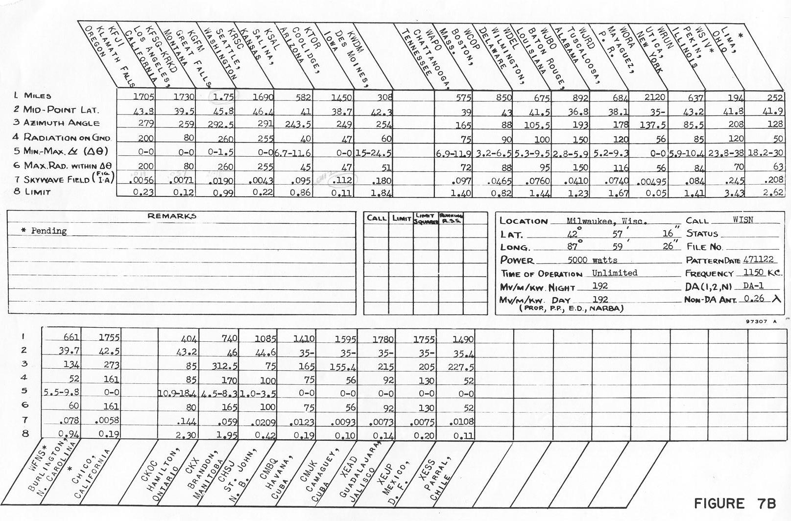
WISN night time allocation study
Back in 1941, nighttime interference was taken seriously. The nighttime allocation study (on 1150 KHz, WISN’s former frequency) includes co-channel stations in the US, Canada, Cuba, and Mexico.
WISN night time allocation ma
The array consisted of four Blaw-Knox self-supporting towers in a rectangle. Notice the lack of fencing, warning signs, and the like around the towers.
WISN antenna array
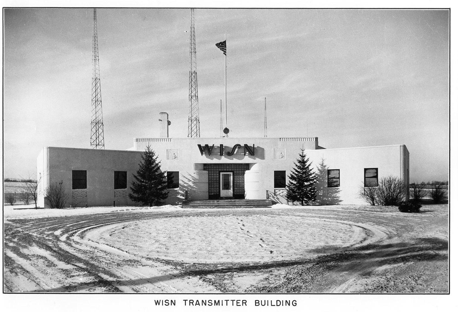
From the front of the transmitter building
WISN transmitter site, 1941
The site looks well designed, no doubt manned during operation, which at the time would likely be 6 am to midnight except under special circumstances. Most of these old transmitter sites had full kitchens, bathrooms, and occasionally a bunk room. The transmitter operators where required to have 1st telephone licenses from the FCC. There is only one manned transmitter site in the US that I know about; Mount Mansfield, VT. There, WCAX, WPTZ, WETK, and VPR have their transmitters.
WISN RCA BT-5E transmitter, 1941
The WISN RCA BT5E transmitter looks huge for that power level. Back in the day when AM was king, these units were designed to stay on the air, no matter what. I don’t know too much about this model transmitter, but if it is like other RCA/GE models from the same era, it has redundant everything.
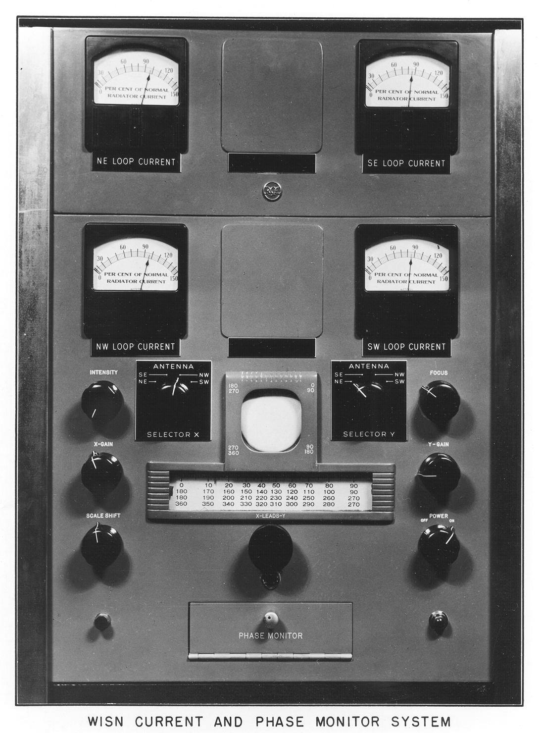
RCA AM antenna monitor
Old school antenna monitor. I have never seen one of these in operation, however, as I understand it, the scope was used to compare the phase relationship of each tower against the reference tower.
These pictures are of the WISN 1150 array was it was in 1941. Since then, the station has changed frequencies to 1130 KHz and increased power to 50,000 watts daytime/10,000 watts night time. The daytime array consists of six towers and the night time array has nine towers, all of which are 90 degrees.
Special thanks to John A. for sending these pictures along.