Occasional reader Jeffery asks a good question, which I will attempt to answer here in simple terms. Phasing, when used with antennas, refers to the relationship that two or more radiating elements share with the waveform being transmitted. It is used to create an RF radiation pattern by adding energy to the wavefront in one direction by taking energy away from the wavefront in another direction.
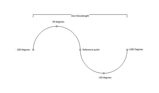
Phasing is often described as +/- X number of degrees from a reference point. Graphically, it would look like this:
One wavelength with +/- 180 degrees notated
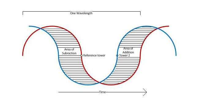
The reference point can be changed to any point on the waveform, in radio applications it is usually oriented around +/- 180 degrees. If the reference point is a single tower or element then this would be the end of the story. Add a second tower to this system and it would look something like this:
Double waveform
In this picture we have two waves being radiated from two separate elements. These elements are spaced 100 degrees apart and tower #2 is phased to +90 degrees. RF generator is coupled to both towers via a power divider, the reference tower (tower #1) is feed with 57% of the power that tower #2 is being feed. Thus, the ratio of power to the respective towers would be 57:42. Thus, if tower one had a power reading of 1.00, tower two would be 0.74. The towers are on a north/south line with the reference tower bearing 180° from tower #2. In the area of subtraction, the waveforms from each tower cancel each other out to some radiating less power toward the south; in the area of addition, the waveforms sum to create a more powerful waveform, radiating more power towards the north.
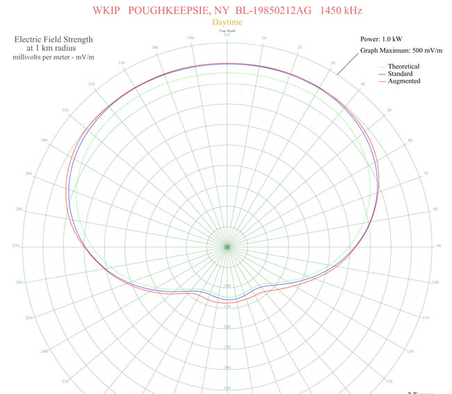
This is a typical two tower array, however, there are two slight differences; the reference tower is 215 degrees tall, tower two is 90 degrees tall. This is yet another use of “degrees” to relate electrical length or separations. The second, more notable distinction is that this array is Directional daytime, and non-directional night time, which is the opposite of most AM stations in this country.
Electrical height can also be described as a function of wave length, e.g. 1/4 wave, 1/2 wave, etc. Most AM towers in this country are 1/4 wave length, which equates to 90 degrees. Often, higher powered stations, and some low powered stations put up towers near 1/2 wavelength due to the better ground wave performance of those towers. At lower dial positions, a 1/2 wave tower becomes an expensive proposition due to the height required.
In theory, an unlimited number of towers can be used to create a pattern by introducing nulls (areas of subtraction) and lobes (areas of addition). In practice, the highest number of towers I’ve ever heard being used in an AM directional array is twelve; KFXR 1190, Dallas, TX. There may be others, too.
An excellent resource for AM directional antenna technical information is Jack Layton’sDirectional Antennas Made Simple, which is out of print but available from various sources.
This is a youtube video of a Police song from the 1980s received via skywave and recorded off-air on an AM radio.
Video Description:
The classic 1983 #1 smash hit, as received in analog C-Quam AM Stereo… in Japan… via nighttime skywave in the Tokyo area, roughly 500 miles away from Sapporo (ed: where the station is located). The audio quality is among the best I’ve ever heard from analog AM radio, thanks in large part to an excellent wideband receiver, very quiet band conditions, and the Orban Optimod-AM 9100 audio processor being used by HBC Radio to its maximum extent: 12.5 kHz audio bandwidth with stereo enhancement added (above and beyond the amount naturally provided by the matrix processing used by AM Stereo).
Absolute trash, I tell you. Just awful.
Of course, I know several FM stations around here that wished they sounded as good. Naturally, Japan, they have sought to minimize night-time interference problems by limiting the number of stations on the air and enforcing the rules and regulations in place to protect those stations on the air. They also seem to allow greater bandwidth, out to 12.5 KHz in spite of the narrower channel allocations (9 KHz in ITU regions I and III, vs 10 KHz here in the US, ITU region II). One other thing to note, there is no digital buzz saw occupying several channels of the broadcast spectrum. Keep in mind, this was received in Tokyo, likely a very high noise environment.
I was trying to find out the power level of the transmitter, the call sign is JOHR in Sapporo Japan, frequency is 1287 KHz. HBC is the Hokkaido Broadcasting Company, a privately held company. The state-run radio outlets in Japan are NHK, which has several radio and TV stations throughout the islands.
Anyway, AM is dead. Killed by the very owners of the broadcasting companies themselves with help from the NAB. They are the ones that petitioned the FCC to loosen up the allocations and allow more and more stations to be crammed into the band. That is old news. The new news is same forces that killed AM radio are diligently working their magic on the FM band as well. More stations, translators, digital IBOC nonsense that doesn’t work, more of everything. After all, more is better. Until it is not. Then it’s too late.
Eventually, disaster will strike. It can range from a fire at the transmitter site to a tornado at the studio. Someday, every station on the air will be knocked off at the worst possible moment. It is the law of nature. Perhaps the most difficult disaster to recover from is the loss of a tower at a transmitter site. An FM tower holds the antenna, therefore, finding a tower or building nearby and placing a temporary antenna there will get the station back on the air in a reasonable fashion.
An AM tower is the antenna, which is much harder to replicate. One possible solution is to use a temporary wire antenna while the tower is being rebuilt. This is allowed in FCC 73.1680 emergency antennas, provided the commission is notified of the situation by informal letter. Directional stations must operate at 25% or less of the station’s licensed power, or demonstrate that radiation limits are not being exceeded in any direction. That usually can be accomplished by taking a set of monitor points.
A wire antenna can come in several configurations:
The fastest to deploy is the random-length end-fed wire. This can normally be attached to the existing ATU and tuned up with components on hand. It requires having an OIB, generator, and receiver to tune, which not every station has. In addition to that, extra components may be needed in the ATU for tuning purposes.
The next easiest is a tower-length wire ready to deploy. This is a length of wire equal to the height of the tower, with insulators and supports. The wire should be supported as high above ground as possible using trees, wooden poles, etc. Still requires having an OIB, generator, and receiver to tune. Likely to be within the tuning limits of the ATU components on hand.
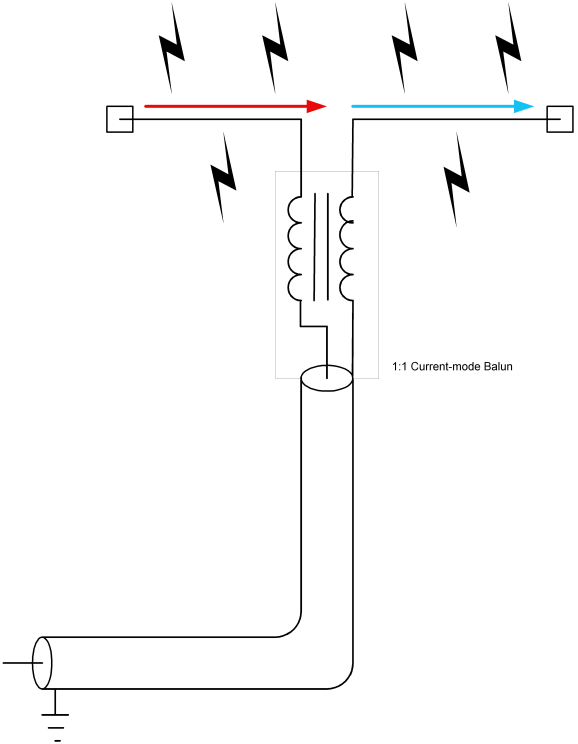
A 1/2 wave dipole tuned for 50 ohms. This can be connected directly to the transmitter output, thus is the best solution if the ATUs were damaged or otherwise not serviceable. In this situation, two 1/4 wavelengths of wire are coupled at the center using a 1:1 balun. Again, this antenna should be supported as high above ground as possible using trees, poles, and other non-conductive supports. Can be installed in a V, inverted V, or L shape as required.
All three of these choices would likely limit transmitter power output to 1-2 KW. Choice 3 likely represents the most efficient radiator and can be fabricated ahead of time and stored at the transmitter site.
1/2 wave dipole with 1:1 balun
To make a 1/2 wave dipole, cut two lengths of wire using the formula L(feet)=246/F(MHz). This formula does not account for a velocity factor of 90%, which is typical for stranded wire. The reason is, since an MF dipole antenna is necessarily going to be lower than 1/2 wavelength, it is better to start the antenna a little long and trim it to size for a 50-ohm impedance. If commercially made insulators are not available, insulators can be made from non-conductive materials like PVC conduit, PEX, plexiglass, etc. The insulators on the ends of the wire need to account for the voltage peak that will occur there. If small “dogbone” type porcelain insulators are used, string three or four of them together using nylon or poly rope. The insulator needs to be able to withstand 8-10 KW of power under full modulation.
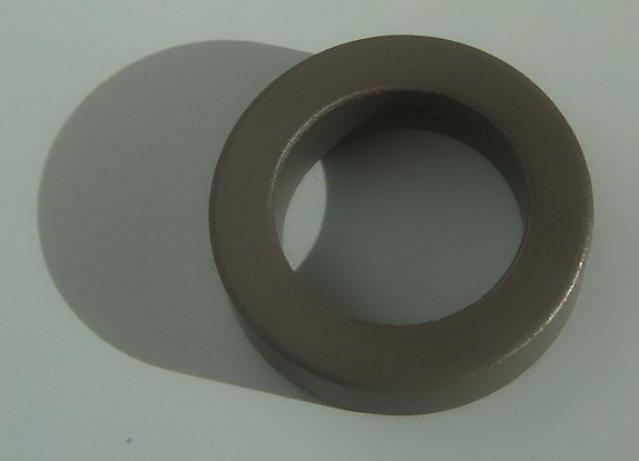
A 1:1 balun will distribute the RF currents evenly on both wires, which will help improve efficiency and coverage. Most Ham Radio Baluns are not designed to work below 1.8 MHz and therefore, will not work for this purpose. A balun can be made with a ferrite toroid made from 68, 73, 77, or type F material. A good choice would be Amidon FT-290-77 or FT-290-F. The type F material has a higher AL value, thus fewer turns are needed. In addition to that, high voltage insulated wire should be used to wind the balun.
1/2 wave dipole antenna current voltage distribution
Since, in a 1/2 wave dipole configuration, the voltage is at a minimum at the center of the antenna, and current is at a maximum, some attention needs to be paid to wire size as well.
Amidon ferrite torroid core
To give a good idea of wire sizes required, some basic information is needed. For a 1 KW station, it is assumed that the carrier will be modulated to 100 percent, therefore the peak envelope power will be 4 KW. If the station is asymmetrically modulated, add another kilowatt. Therefore, the maximum current formula is I=√(P/R). P is the power in watts, or 5,000 and R is the radiation resistance or 50 ohms, thus I=√(5000/50) or 10 amps. The maximum voltage is E=√(P x R) or E=√ (5000 x 50) or 500 volts. For a safety factor, multiplying these values by 1.5 is recommended. That will likely account for any impedance differences due to ground proximity and so forth. Therefore for a 1 KW station, the dipole antenna should be designed for 15 amps and 750 volts.
For a 2 KW station the peak envelope power for an asymmetrically modulated transmitter is 10 KW, thus it follows that 30 amps and 1500 volts are safe working figures.
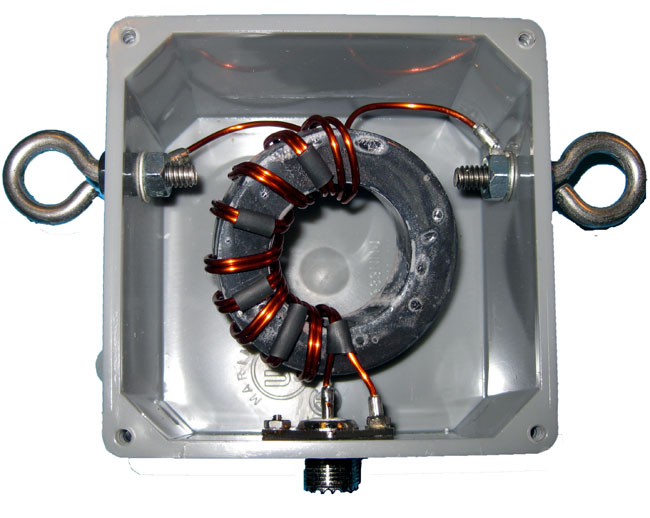
With the proper torroid core, a turns count of 7-10 turns bifilar will suffice. Since it is a 1:1 balun, the turns count on both sides of the transformer will be the same. The balun then should be placed in a suitable water proof housing designed to be attached to the center of the dipole antenna. This is a good example of a commercially available 5 KW 1:1 balun for amateur radio use:
1:1 balun designed for center of 1/2 wave dipole antenna
The antenna can be fed with RG-8, RG-8X, RG-8A, RG-214 or any other coax this is capable of handling the peak envelope power of the radio station. The connector can be UHF, N, LC, etc. In some cases, the may be easier to simply omit the connector and connect the coax to the balun using some type of strain relief on the cable coming out of the box.
Once this antenna is made, a bit of tuning may be required to bring it to 50 ohms. This can be done with a bridge and generator, or with the transmitter on low power. Either way, the measurements must be taken with the antenna at operating height as the distance to ground will effect the termination point impedance. It may require some trial and error.
In all, a good backup antenna can be made for about $50-60 or so. A little bit more if fancy transmission line is used. Well worth the expense and effort to have something ready to go in a moment’s notice.
Update: I’ve been fooling around with this on EZNEC, it may not be that easy to do, especially with the lower frequencies in the AM band. The antenna needs to be at least 0.06 wave length above ground to perform correctly. Somewhat lower over better ground conductivity, e.g. ground radials. Even at this height, it needs to be lengthened significantly to get the feed point impedance close to 50 ohms.
There is a propensity among radio engineers to save old equipment. Sometimes I look at something and think, “Man, that cost a lot of money ten or twenty years ago.” Truth be told, much of what is saved will never be used again. This equipment should be scraped or donated to someone who might find it useful. One thing that is most appreciated by Amateur Radio (AKA Ham) operators is old 1 KW tube type AM transmitters. Ham operators love these things and with good reason.
A fair amount of repair work, some cleaning, and a bit of reworking will turn what might have been a useless dust collector into a 160 or 80-meter AM rig and with a good story to boot.
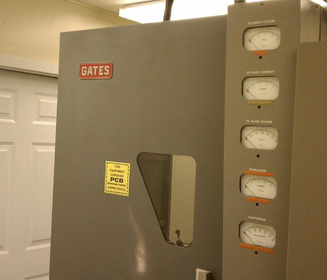
Personally, I’d rather see a Gates BC1T or RCA BTA1R off to a new home than off to the scrap yard. To that end, today we unloaded the BC1T at WLNA to a willing ham. This particular transmitter had last run in 2001 or so and was used as a spare parts supply for other BC1T transmitters owned by the same company. There was no way it would ever work again and truth be told, it really wasn’t needed any longer anyway. Since the Harris MW5B was replaced as the main transmitter by a BE AM6A, the backup transmitter was never used.
Gates BC1T transmitter
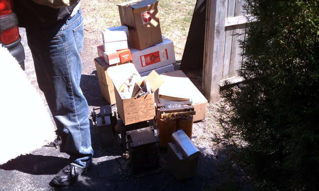
John Aegerter, a frequent commenter on this blog, drove all the way from Madison, Wisconsin to pick it up. Prior to picking up, I removed all of the tubes, transformers, crystals, and glass envelope time delay relays. I packed up the glass objects in a box.
Gates BC1T tubes, transformers and spares
There were several spare tubes and parts which are no longer needed. These went with the rig, along with whatever manuals I could find.
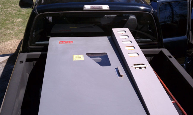
Gates BC1T loaded into pickup truck
The transmitter was then loaded into the back of a Dodge Ram 2500 pickup truck and tarped for its trip back to Wisconsin.