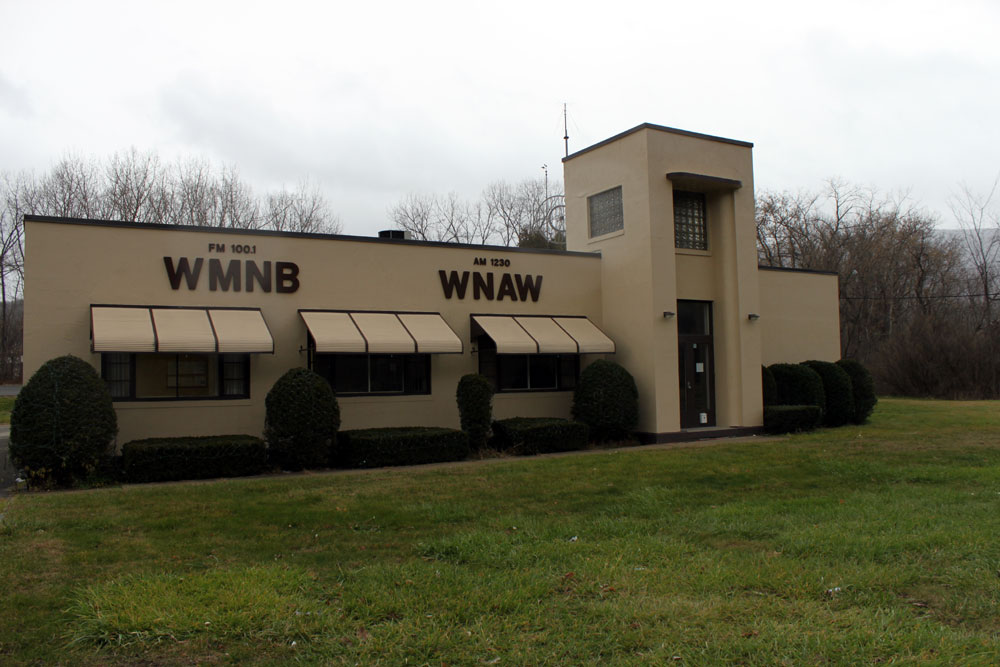
Troubles at the AM tower; I don’t know why, it won’t switch power.
Over the phone I can tell, the program director’s day is not going very well.
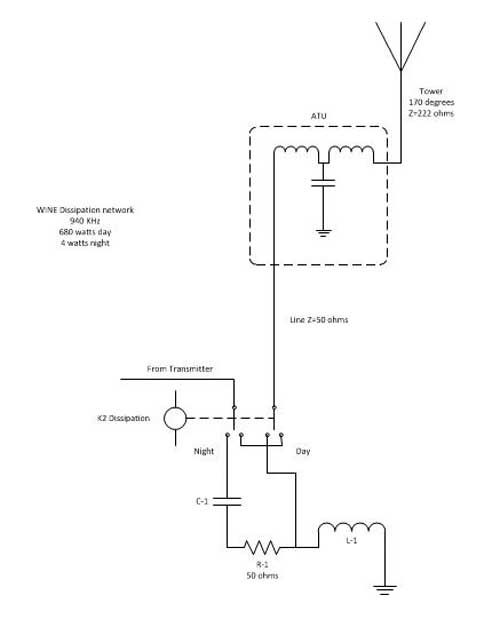
Press the “day” button but there is no kerchunk, the directional coupler shows the load is junk.
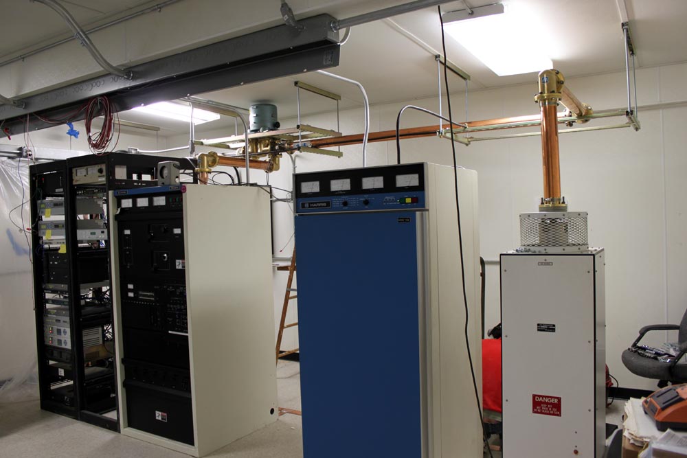
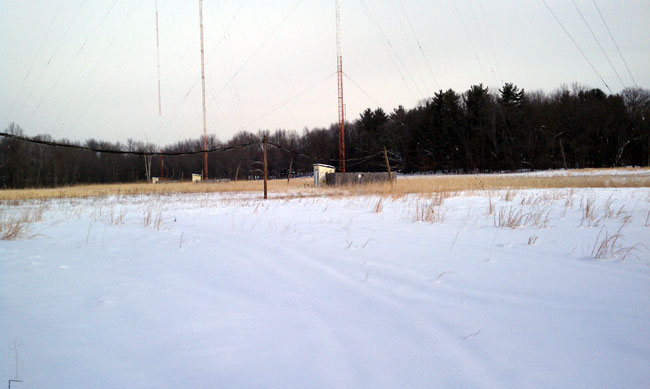
Out into the big field, I go to find the problem quickly and fix it just so.
The wind is cold, the snow is deep, I think of the contract terms I must keep.
Reaching the tuning house, take out the keys, lock, do not be frozen, please.
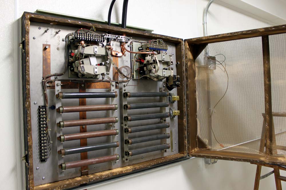
Once inside, there I find, no big surprise, the mice have been a working this pre-sunrise.
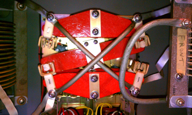
A nest they have build in a most inconvenient place, in the back of the phasor wiring chase.
Oh, the wires they have chewed, the circuit’s destroyed, all for the lack of mousetraps deployed.
As I reach in to clean out the mess, the smell of mouse makes me gag, I confess.
The fuses are blown, the contactor is jammed, perhaps, if I am lucky, I can move it by hand.
A large screwdriver strategically employed, I pry up slowly, further damage to avoid.
The bar thunks up, the contacts engage, the transmitter is ready to apply amperage.
Call on the cell phone, tell them it’s fixed, stand back and watch the base current meter, transfixed.
Then; Up it goes! Wonderful radio frequency current flows!
I clean up, lock the door, lock the gate, carrying bad news the owner will hate.
The damage is grave, the repair bill is steep, if a good relationship with the FCC you desire to keep.
Business is off, the accounts are low, is this really necessary, he wants to know.
The terms of the license are your obligation to keep, getting caught out of tolerance will not be cheap.
Looking forlorn, the owner says in disgust, it is only the AM, but fix it if you must.
Happy as a lark, with a song in my heart, I dig though the manual and order the part.
Time to go home, eat breakfast, brush teeth, take a shower. I have another client to see before the noon hour.
Dedicated to all those who have been there, done that and the breed of RF men and broadcast engineers who are slowly fading away.