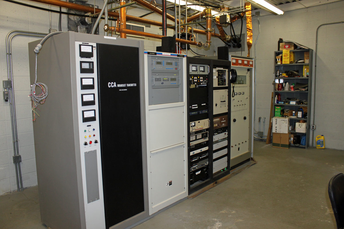
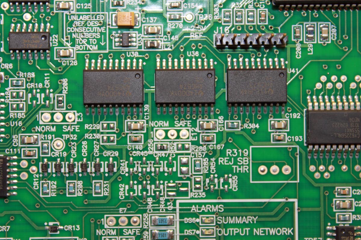
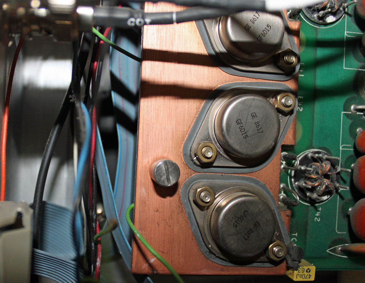
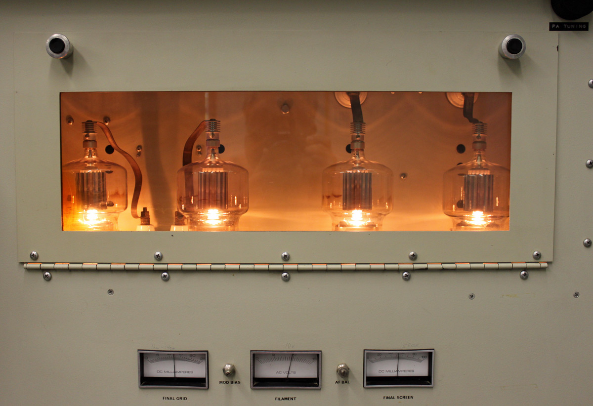
In service as a backup unit at WALL 1340 KHz in Middletown, NY:
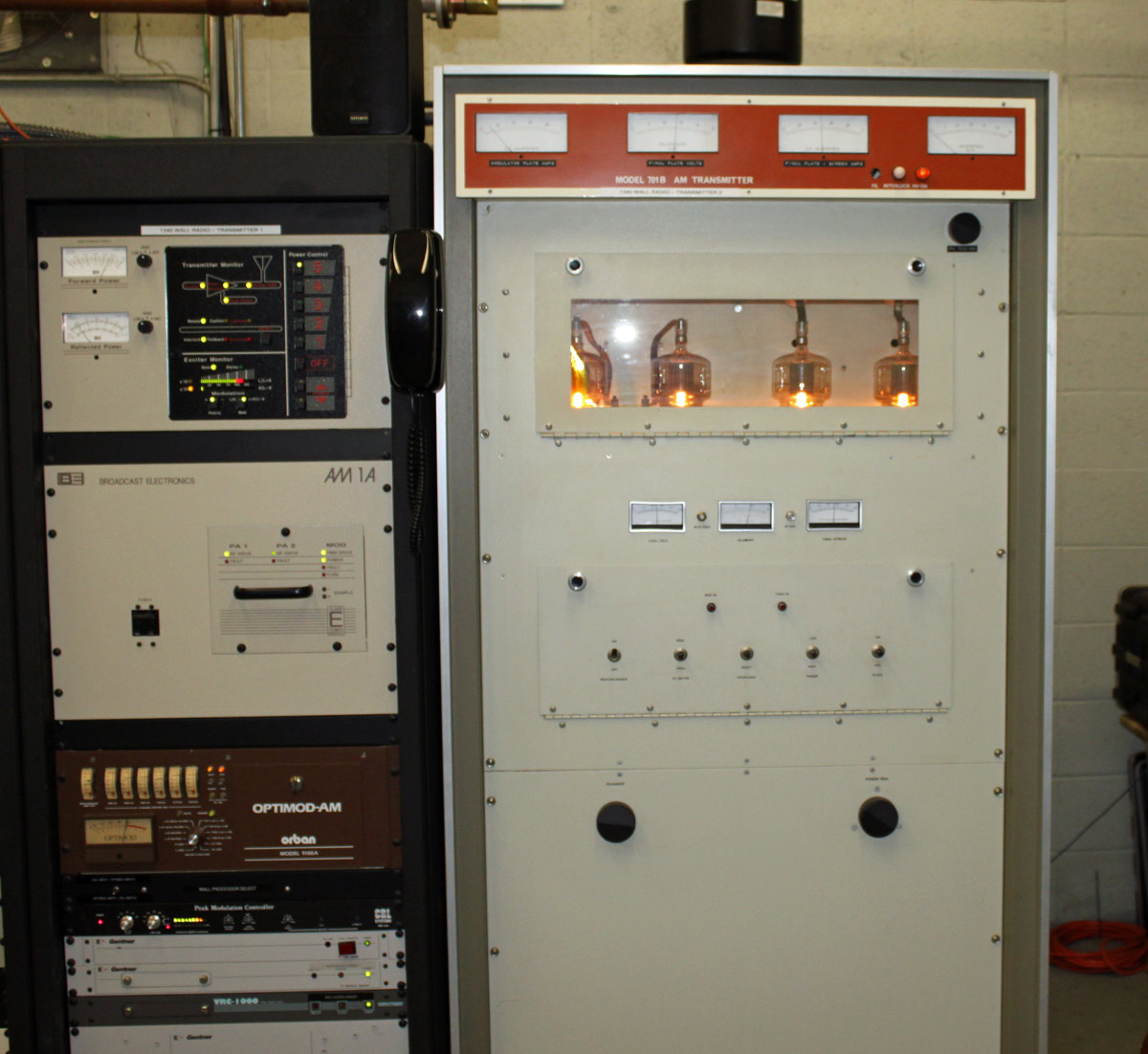
I believe the Cetec transmitter is from the early 70s. I wouldn’t really call it old, we have much older units in the field that are still in backup service. WALL itself has been on the air since 1942 from this site. The tower out back was replaced in the mid ’90s and is 147 degrees tall. It broadcasts the “True Oldies Channel” and is currently owned by Cumulus, soon to be Townsquare.
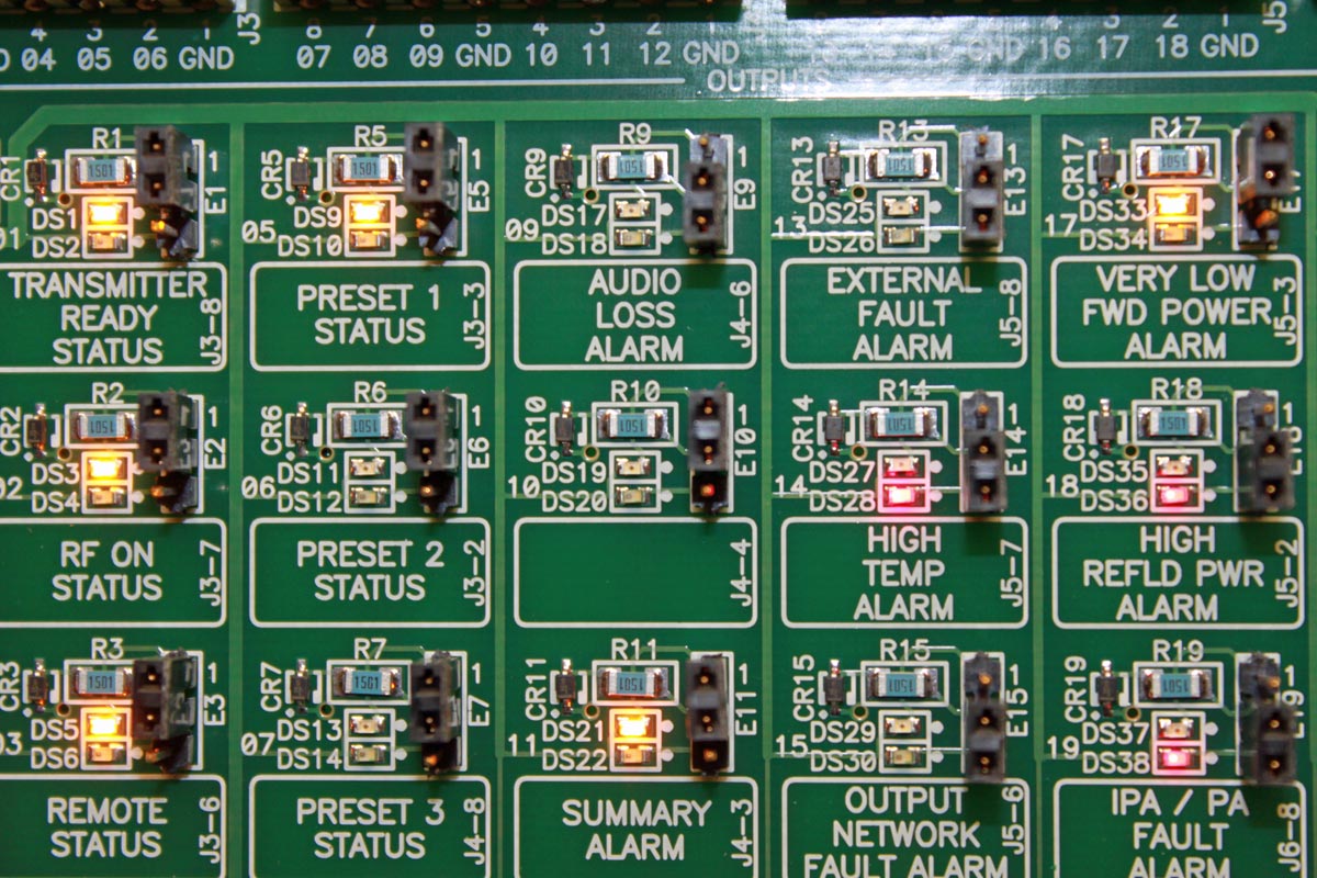
The site is also home to sister station WRRV (92.7 MHz) which has a side mounted antenna near the top of the WALL tower. We are currently reconnecting the CCA transmitter as the backup for WRRV. That unit is also from the early 1970’s.