WISN 1130 AM has been on the air since 1922, although not always with those call letters. In an interesting twist, the license was granted to the local newspaper, the Wisconsin News, and the Milwaukee School of Engineering. Initially, both entities were programming the station, however, by about 1925, the newspaper was responsible for programming and the engineering school was responsible for technical operations.
In 1941, the station increased power from 1,000 watts to 5,000 watts and added nighttime service. This is a series of pictures from that time period.
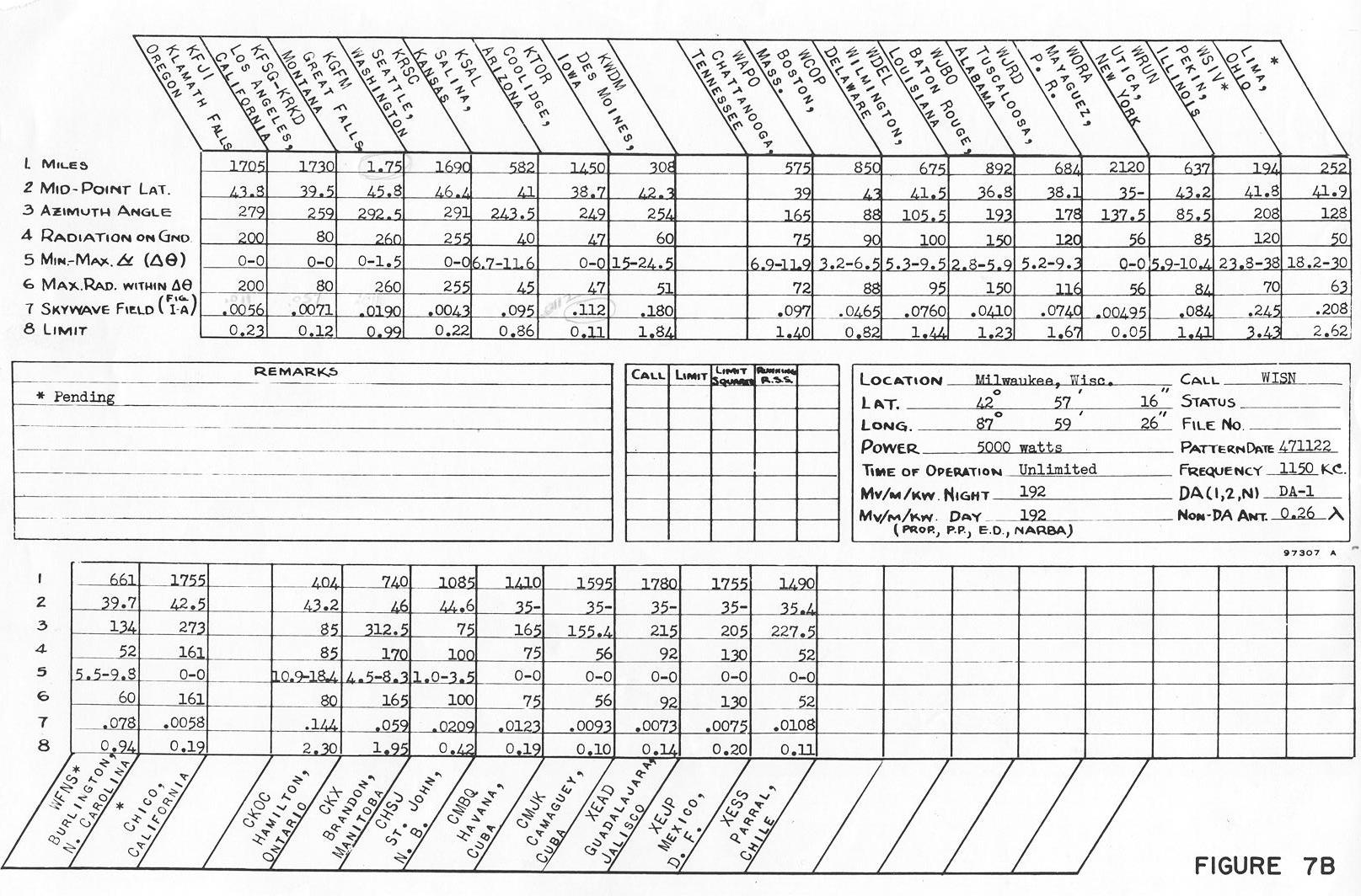
Back in 1941, nighttime interference was taken seriously. The nighttime allocation study (on 1150 KHz, WISN’s former frequency) includes co-channel stations in the US, Canada, Cuba, and Mexico.

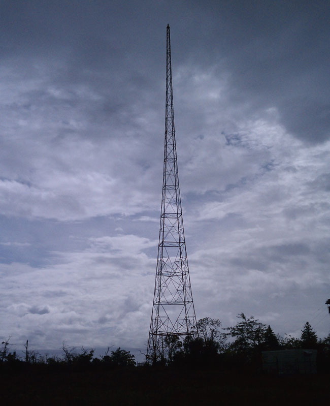
The array consisted of four Blaw-Knox self-supporting towers in a rectangle. Notice the lack of fencing, warning signs, and the like around the towers.

From the front of the transmitter building
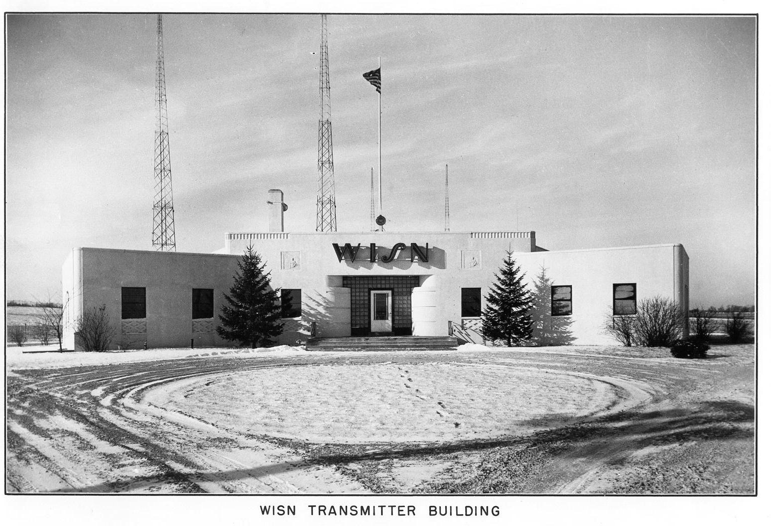
The site looks well designed, no doubt manned during operation, which at the time would likely be 6 am to midnight except under special circumstances. Most of these old transmitter sites had full kitchens, bathrooms, and occasionally a bunk room. The transmitter operators where required to have 1st telephone licenses from the FCC. There is only one manned transmitter site in the US that I know about; Mount Mansfield, VT. There, WCAX, WPTZ, WETK, and VPR have their transmitters.

The WISN RCA BT5E transmitter looks huge for that power level. Back in the day when AM was king, these units were designed to stay on the air, no matter what. I don’t know too much about this model transmitter, but if it is like other RCA/GE models from the same era, it has redundant everything.
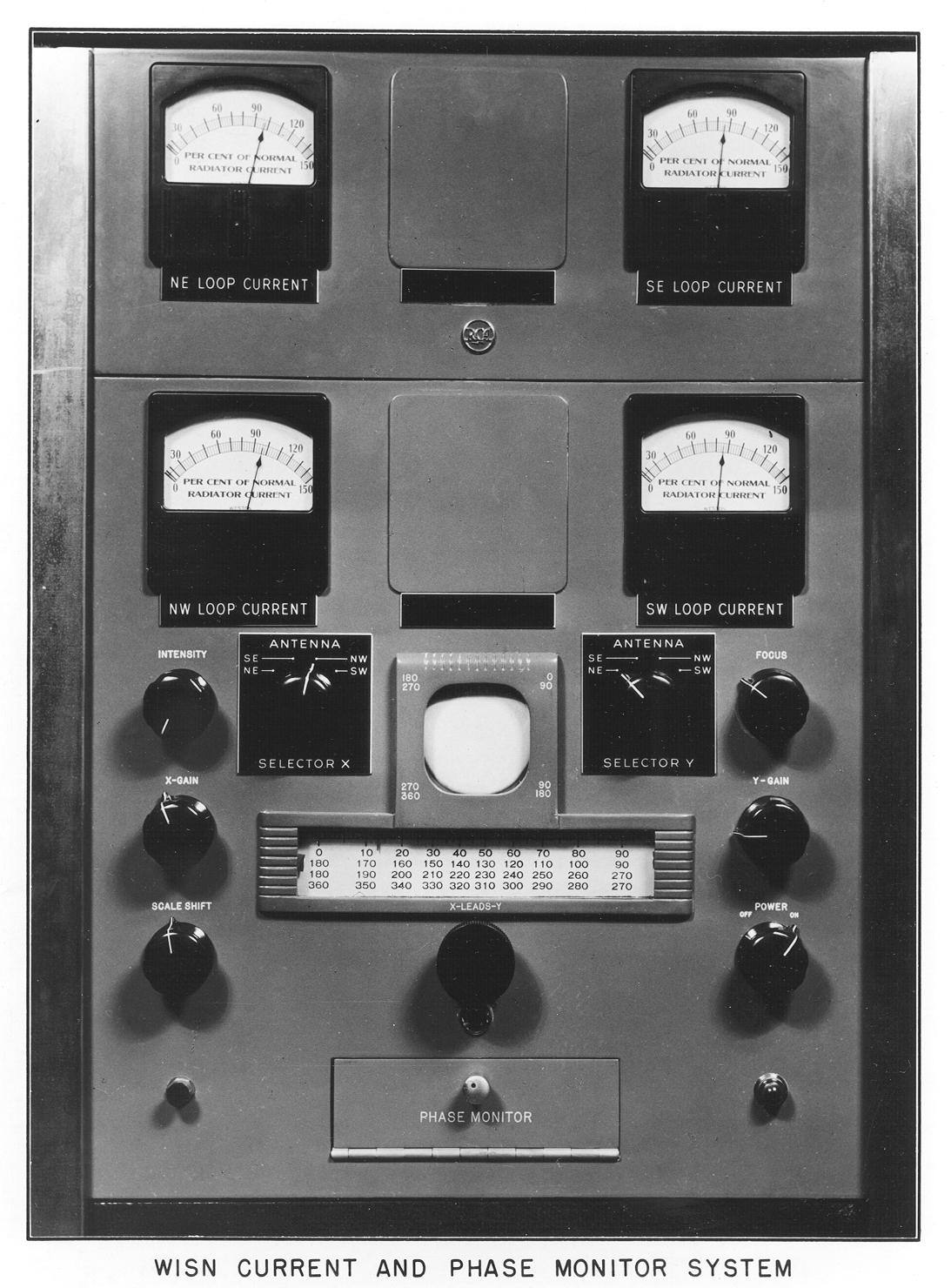
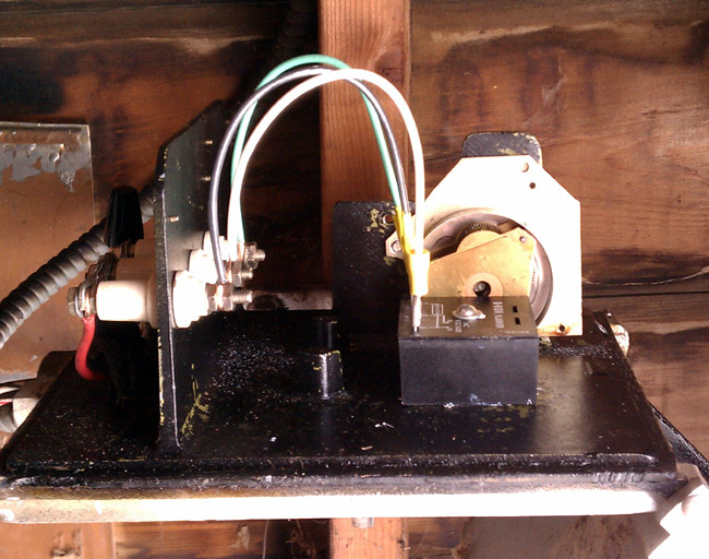
Old school antenna monitor. I have never seen one of these in operation, however, as I understand it, the scope was used to compare the phase relationship of each tower against the reference tower.
These pictures are of the WISN 1150 array was it was in 1941. Since then, the station has changed frequencies to 1130 KHz and increased power to 50,000 watts daytime/10,000 watts night time. The daytime array consists of six towers and the night time array has nine towers, all of which are 90 degrees.
Special thanks to John A. for sending these pictures along.