I found that question while perusing my search engine statistics today. The short answer in theory is yes. If you are a copper thief, it will most likely look like this:
That being the case, however, it is much more likely that an RF burn will result if one comes in contact with an energized antenna or transmission line. Even small RF burns are painful, large ones can be nasty things. RF burns occur because of the skin effect, that is to say, the higher the frequency of the AC waveform, the closer to the surface of any given conductor the current will flow. It is the reason why five-watt STL transmitters on 950 MHz use 7/8 or 1 5/8 inch cable to reduce losses.
When a human body part comes in contact with an energized RF antenna, the body part becomes part of the circuit, thus it follows the same principles. The extremity that is making contact will have its skin burned off. It also smells bad.
Getting an RF burn is a painful lesson on what not to come in contact with around a transmitter site. But, that is not all. Simply being in close proximity to radiating elements of antennas will induce body tissue heating, just like a microwave oven. This can lead to all sorts of short-term and long-term damage to organs and other problems.
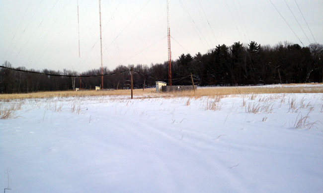
Therefore, the best thing is to avoid radio and cellular towers if you do not know what you are doing. Stay out of fenced-in areas around tower bases. No matter how tempting that copper may look, you could be seriously injured or killed if you cut the wrong thing.
Troubles at the AM tower; I don’t know why, it won’t switch power. Over the phone I can tell, the program director’s day is not going very well. Press the “day” button but there is no kerchunk, the directional coupler shows the load is junk. Out into the big field, I go to find the problem quickly and fix it just so. The wind is cold, the snow is deep, I think of the contract terms I must keep. Reaching the tuning house, take out the keys, lock, do not be frozen, please. Once inside, there I find, no big surprise, the mice have been a working this pre-sunrise. A nest they have build in a most inconvenient place, in the back of the phasor wiring chase. Oh, the wires they have chewed, the circuit’s destroyed, all for the lack of mousetraps deployed. As I reach in to clean out the mess, the smell of mouse makes me gag, I confess. The fuses are blown, the contactor is jammed, perhaps, if I am lucky, I can move it by hand. A large screwdriver strategically employed, I pry up slowly, further damage to avoid. The bar thunks up, the contacts engage, the transmitter is ready to apply amperage. Call on the cell phone, tell them it’s fixed, stand back and watch the base current meter, transfixed. Then; Up it goes! Wonderful radio frequency current flows! I clean up, lock the door, lock the gate, carrying bad news the owner will hate. The damage is grave, the repair bill is steep, if a good relationship with the FCC you desire to keep. Business is off, the accounts are low, is this really necessary, he wants to know. The terms of the license are your obligation to keep, getting caught out of tolerance will not be cheap. Looking forlorn, the owner says in disgust, it is only the AM, but fix it if you must. Happy as a lark, with a song in my heart, I dig though the manual and order the part. Time to go home, eat breakfast, brush teeth, take a shower. I have another client to see before the noon hour.
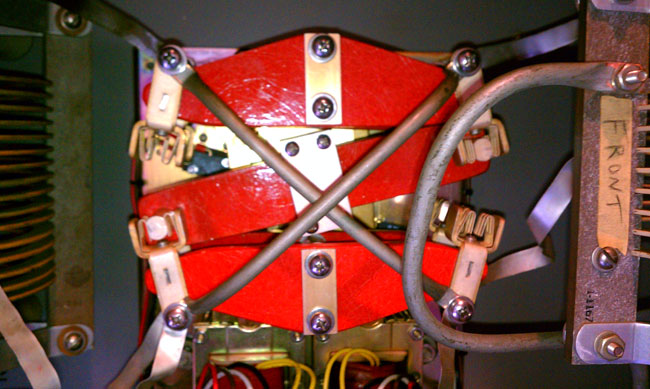
40 amp RF contactor
Dedicated to all those who have been there, done that and the breed of RF men and broadcast engineers who are slowly fading away.
This is a situation that is and will be playing out over and over throughout the country as the decay advances. W*** signed on the air in March 1963. I believe this is the original tower:
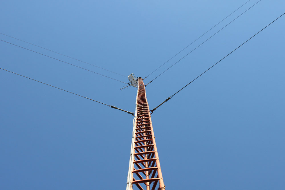
W*** tower
As you can clearly see from this picture, this tower has several problems. Aside from the loose guy wires, the rust, and general structural decay, it is bent in several places. Currently, the forces are in equilibrium, but for how long, no one knows. It is certainly not safe to climb. At 144 feet, it is no longer required to be marked or lit, thus, over the years, the paint peeled, the weep holes filed up, and the guy wires rusted and loosened, which leaves us with the situation today.
At the transmitter building, there are other issues with the basement flooding, mold, etc. Truth be told, this station makes no money on its own. It would cost several tens of thousands of dollars to fix all these issues, and for what; a high end of the broadcast band class D AM station which has not shown up in the ratings for fifteen years. Once upon a time, it was a surviving, perhaps not thriving, local radio station. Those times have long since passed.
The question is; what to do with it? Sign it off and surrender the license? Fix all the problems and continue to broadcast? Donate it? If so, who would take it? Or, more likely, wait until the tower collapses and deal with it then.
I’d imagine that there are many others just like it dotting the country. On the whole, the AM broadcasters that are viable would be better off if this dead wood was cut away and discarded.
Series excited AM towers require some way to get standard AC across the base insulator to the tower lights if tower lights are required. While many new AM towers do not have base insulators, through the use of a folded unipole, it is still a very popular design and has several technical advantages.
There are two methods for getting 60 Hz AC from zero RF potential to an excited tower:
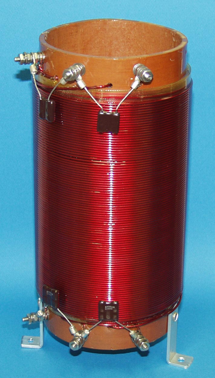
Tower lighting choke
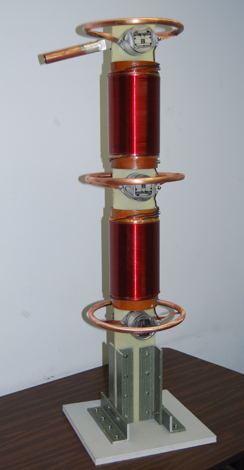
Austin Ring transformer
LBA Group TC-300 tower lighting choke courtesy LBA Group, Inc
When to use it depends on the tower and the RF potential on the base of the tower. For towers that are under 140 electrical degrees (RF) and carrier power levels up to 100 KW, a lighting choke works well. They are simple and less expensive than an isolation transformer. They can be installed inside the ATU cabinet or placed in their own weatherproof enclosure as required. Tower lighting chokes will add series impedance to the base of the tower and needs to be compensated for by adding capacitance to the circuit. This will become more pronounced at the lower end of the band, where, if one is not careful, RF from the tower can be coupled to the transmitter building’s AC mains, which is very undesirable.
Tower lighting chokes generally consist of three separate windings, one for the beacon, one for the side lights, and one for neutral. Their inductance is typically in the 800-1000 µH at 1 MHz region. They can be stacked to increase their peak voltage handling capacity:
LBA Group tower strobe light choke courtesy LBA Group, Inc
Peak voltage is determined by the base impedance and carrier power + modulation. On any AM station these days, a 150% peak modulation figure should be used (125% modulation allowed by FCC rules plus a 25% safety factor). For example, station B has a base impedance of 50Ω (typical 90° guyed tower) and a carrier power of 50 KW. The peak modulation power will be 600 KW. Thus, the peak voltage will be Epeak = √Ppeak x R, or Epeak = √600,000 watts x 50 ohms or 5,477 volts. With higher base impedances, the base current goes down but the base voltage goes up. A typical 140° tower will have a base impedance of 760Ω. Thus the peak base voltage for a 50KW carrier power modulating at 150% will be 21,354 volts. This is the worst case scenario, as few installations are designed that way and every tower impedance is different than the theoretical self impedances given.
For towers over 140 electrical degrees, it is better to use an isolation transformer because of the RF peak voltage/peak current conditions at the base of towers that are electrically tall. The ring transformer design minimizes stray inductance or capacitance at the base of such towers. Austin Insulators (previously Austin Decca) makes a variety of tower base ring isolation transformers. These have varying input and output voltages.
Diagram of typical Austin Ring transformer courtesy Austin Insulators, Inc
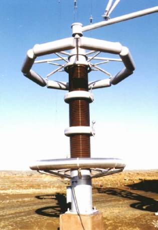
I have seen these at many locations over the years. They are rugged and add only a small bit of capacitive reactance to the base of a typical tower. They also completely isolate the building AC mains from the tower. For very high-power installations, Austin has the A-9600, which was designed for the Navy VLF transmitter towers where base peak RF voltages can run 200,000 volts or more:
Voltage drop is another consideration in tower lighting design. Long runs from the transmitter building to the tower should be on heavy gauge wire and at 230 volts if possible. FAA Circular AC 150/5345-43F “Specification for obstruction lighting equipment” advises that the input voltages for incandescent lighting systems vary by not more than ±3%. Additional tower lighting and painting information can be found in FAA Circular AC 70-7460-1K.