Radio Caroline went on the air forty-nine years ago this weekend, broadcasting from the MV Caroline off the coast of England. Why is this important? Before offshore broadcasting was attempted, in Europe the only radio stations (and TV) were government owned. As such, they had a monopoly over the airwaves and were very restrictive on which groups or types of music they allowed to be broadcast. Many of the so-called “British Invasion” groups like The Beatles, Rolling Stones, The Who, The Kinks, etc got their first airplay on offshore radio stations like Radio Caroline or Radio London.
This video “Radio Caroline – A Day in the Life,” shows what it was like to be an offshore broadcaster:
By the haircuts and music, that appears to be sometime in the eighties.
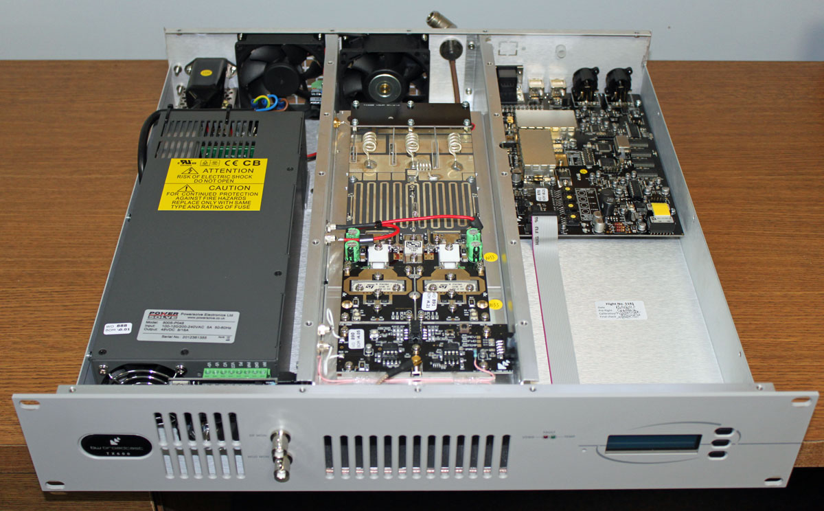
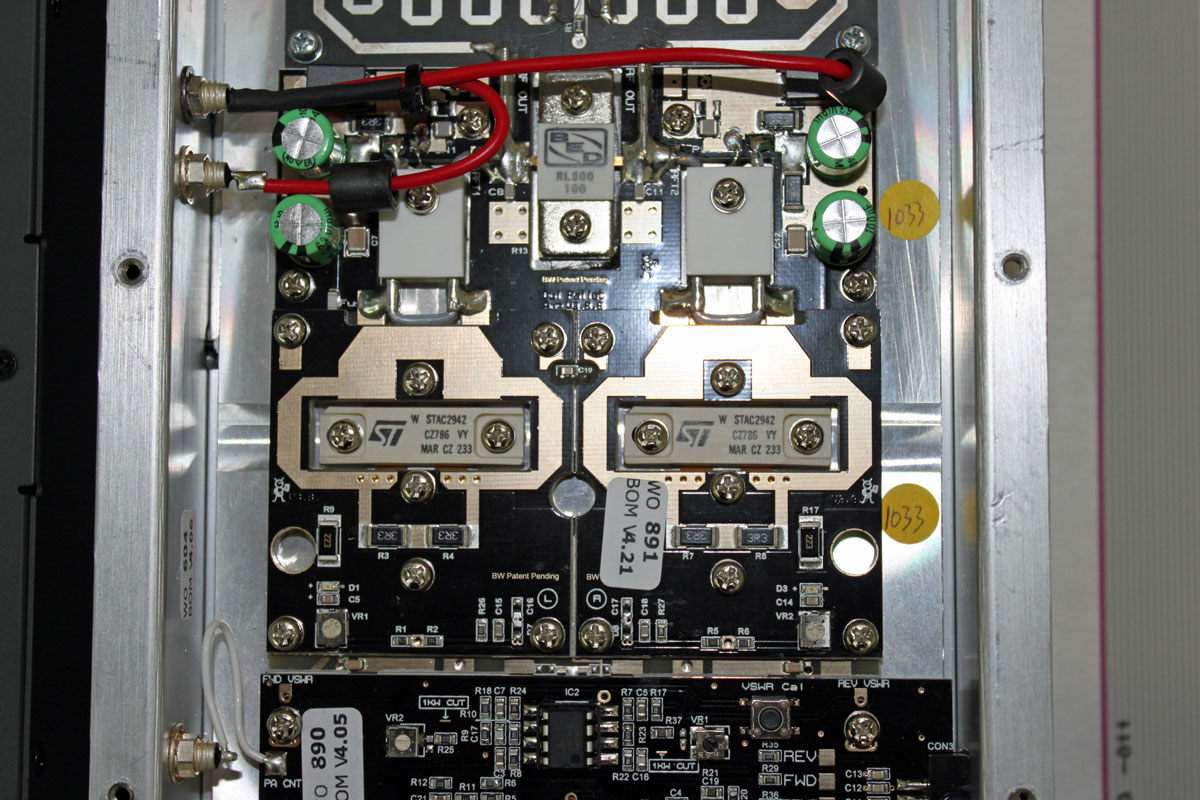
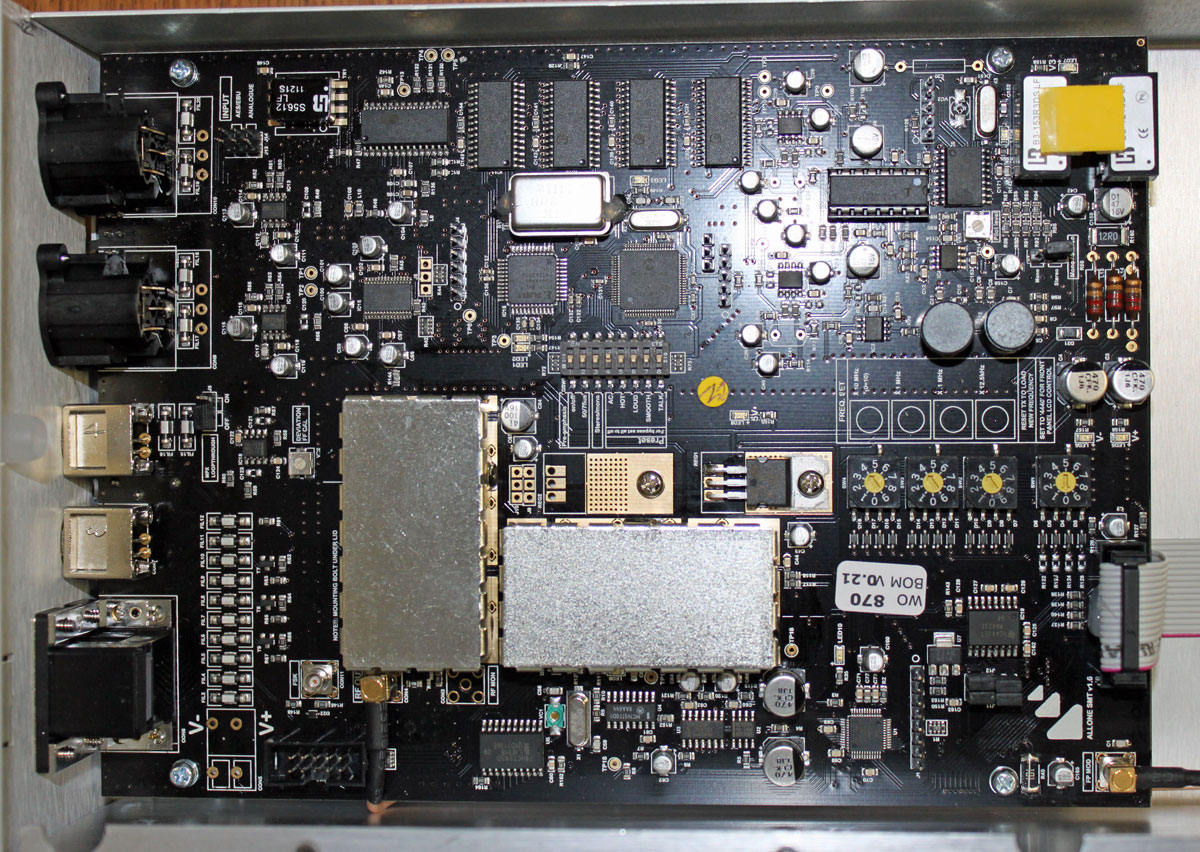
Check out the Radio Caroline website for more information. From 1983 onward, Radio Caroline was broadcast from the MV Ross Revenge. This is an overview of the Ross Revenge transmitter hold. The movie “Pirate Radio” is loosely (very loosely, by most accounts) based on Radio Caroline/Radio London composite.
Radio London was one of the other well-known offshore radio ships.
I am sure that there are other tribute sites with lots of technical information on how they broadcast. Much of offshore radio was outlawed in the late 1960s by several European countries. Radio London signed off on August 14, 1967. Radio Caroline continued on in various iterations until about 1991 or so.
WBCQ is airing a radio ships special on Sunday, March 31, 2013, at 5,110 KHz starting at 6 pm Eastern daylight time (2200 UTC).