It is time, once again, to replace some very old Pacific Recorders BMXII consoles. The Pacific Recorders consoles were very expensive when new, but after 30 years of continuous use, have more than paid for themselves. The replacement console of choice for this installation is a SAS Rubicon. I have installed these units elsewhere and they are the modern equivalent of the PRE BMX.
The heart of the Rubicon system is the 32KD router. Routed audio systems can save a lot of time and effort in a large studio facility installation. Not having to run and terminate multiple analog and digital trunk cables between the rack room and the studio is a huge deal in a six or ten-studio installation project.
The SAS 32KD router and Rubicon console system use a serial TDM bus to communicate and transport audio around. This is a simpler system than packet-switched IP data. Basically, the console surface is a very large, fancy computer control interface. Here are some pictures of the start of the project:
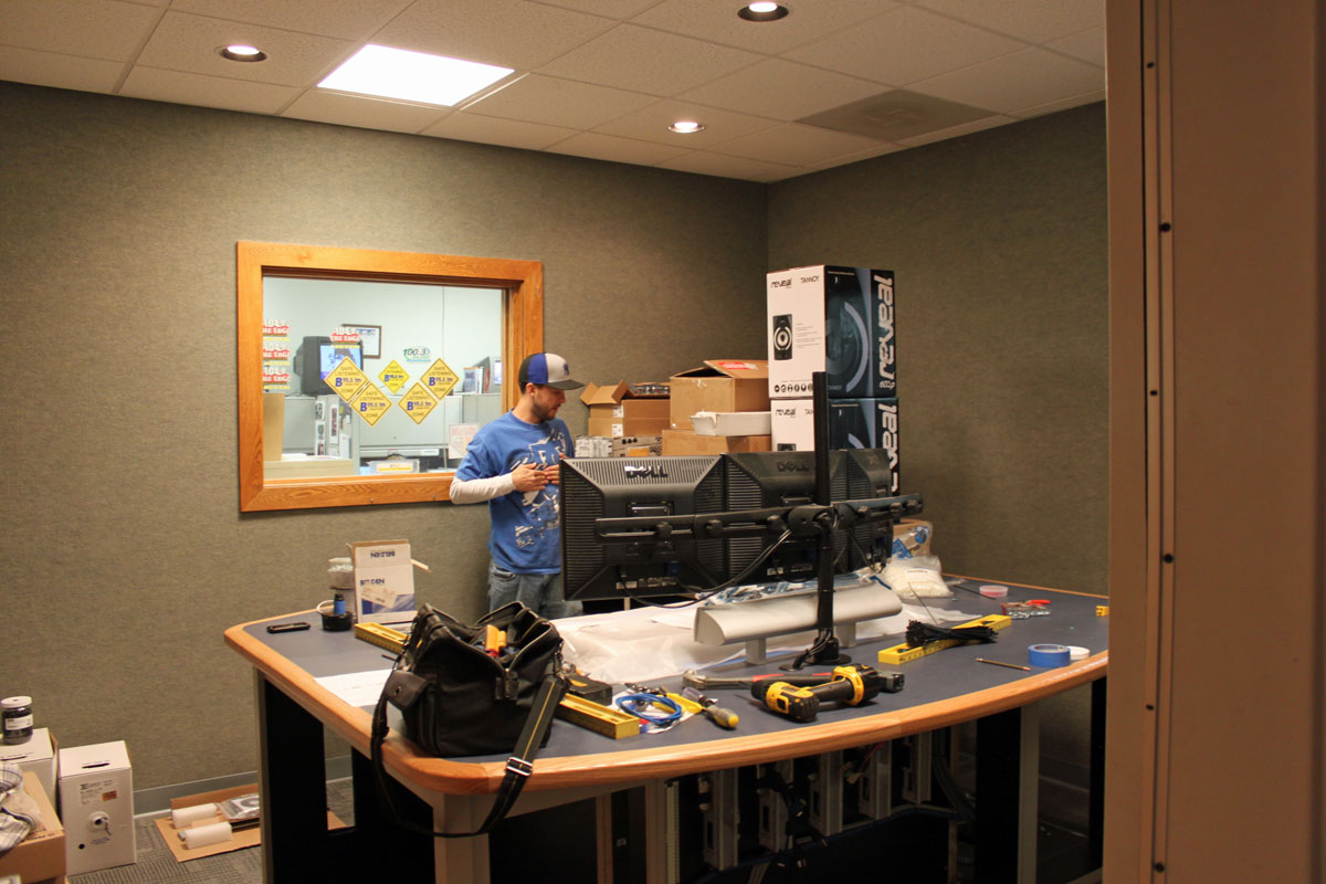
This is the view from the entry door. The furniture was placed last week and the countertop was cut in for the console. The furniture is made by Studio Technology. The pile of yet-to-be-installed equipment:
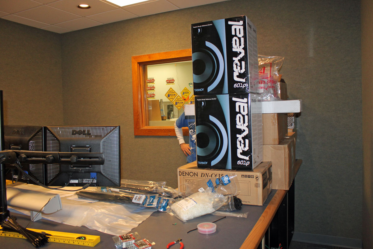
For monitors, we are using the Tanoy 602p near field monitor placed on the table top above the computer screens. This studio will not have a turret. Turrets used to be necessary to hold things like cart machines and CD players. These days the CD players are used so infrequently that it was decided to put them in the side rack under the counter top. Turrets also take up a lot of counter top space that can be put to better use.

Punch blocks and power connections. The red outlets are isolated ground UPS type, the back outlets are feed by the emergency generator power panel. All electric wiring is inside of the metal conduit. The punch blocks are the inputs to the SAS RIO link unit, one 16-pair analog audio cable and ten category 5e shielded cables. The cat 5e is used for computer and TDM data buss to the router.
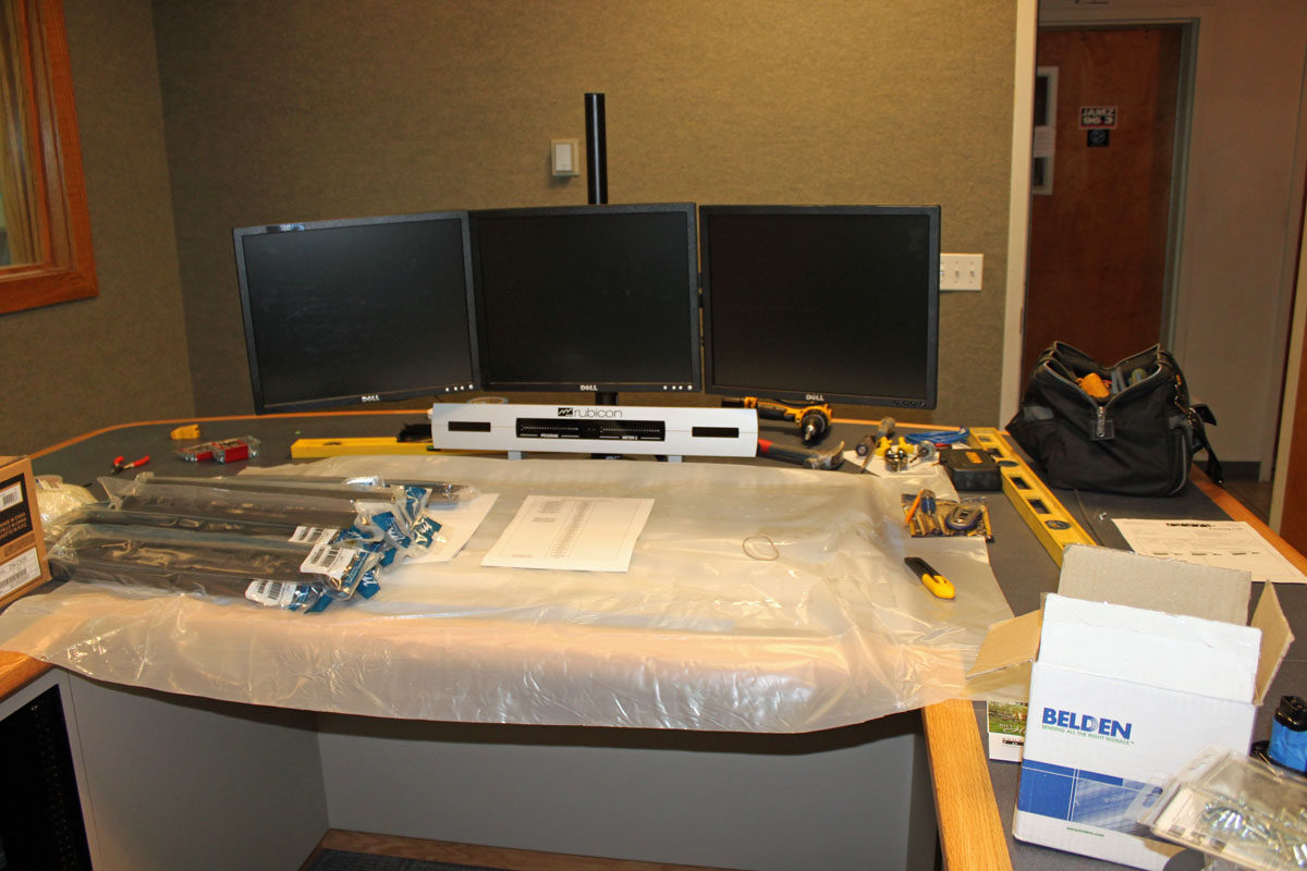
The SAS Rubicon console is cut into the counter top and protected by plastic sheets.
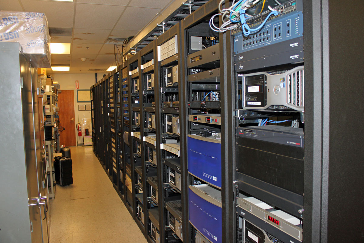
Rack room with 32KD routers. This facility has 9 studios total plus a news room with three work areas.
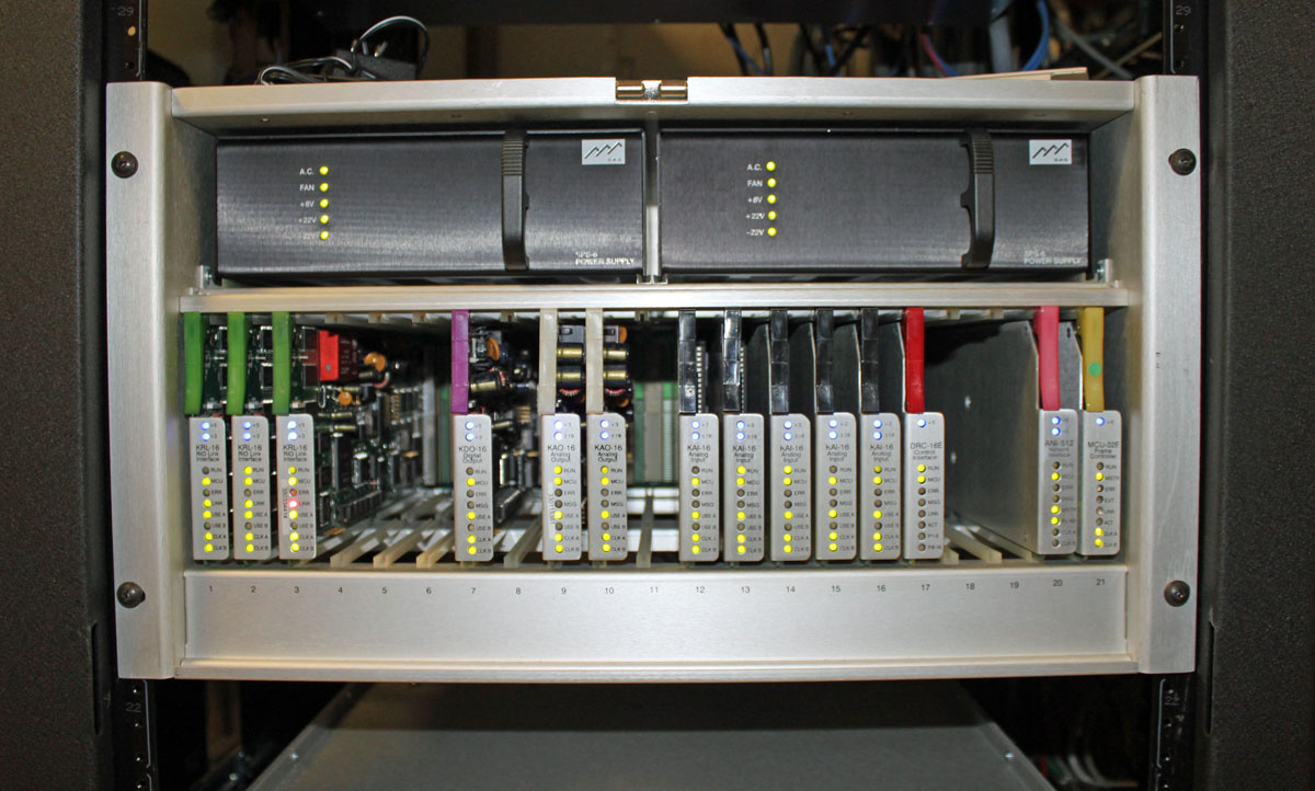
The SAS 32KD router. All audio from the automation systems, satellite feeds and other sources is connected directly to these units. This unit is on line for other studios that have already been converted to the SAS gear.